
Heavy feed mixer

a heavy feed mixer and hydrocarbon feedstock technology, applied in the direction of hydrocarbon oil treatment products, lighting and heating apparatus, separation processes, etc., can solve the problems of reducing output, reducing production costs, adversely affecting the operation and performance of the furnace, etc., to reduce or minimize problems, promote efficient mixing, and reduce or minimize problems

Active Publication Date: 2013-07-30
STONE & WEBSTER PROCESS TECH
View PDF26 Cites 8 Cited by
  • Summary
  • Abstract
  • Description
  • Claims
  • Application Information

AI Technical Summary

Benefits of technology

The apparatus effectively prevents coking and fouling by ensuring complete vaporization of heavy hydrocarbon feedstocks, reducing capital and operating costs while maintaining high efficiency and simplicity, allowing for the production of valuable olefins like ethylene and propylene.

Problems solved by technology

However, the use of these heavier feedstocks having an initial boiling point above 200° C. in a pyrolysis furnace can result in fouling or coking in the convection section tubes, which adversely affects the operation and performance of the furnace.
This significantly reduces output and increases production costs.
However, these approaches require extra processing steps as well as the addition of one or more mixing and separation units prior to the convection section.
This significantly increases the process complexity and results in high capital costs.
However, these approaches require additional piping to deliver the requisite hydrogen-rich stream thereby increasing the complexity and cost.
The need to use process gases such as H2 also adds to the overall operating costs.
However, the apparatus requires a very long vaporization length in order to substantially completely vaporize the hydrocarbon feedstock.
This adds to the capital cost and requires valuable plot space in the furnace convection section.

Method used


Image

  • Heavy feed mixer
  • Heavy feed mixer
  • Heavy feed mixer

Examples


Embodiment Construction

[0040]The above and other objectives of the invention will become more apparent from the following description and illustrative embodiments, which are described in detail with reference to the accompanying drawing. Similar elements in each Figure are designated by like reference numerals and, hence, subsequent detailed descriptions thereof are omitted for brevity.

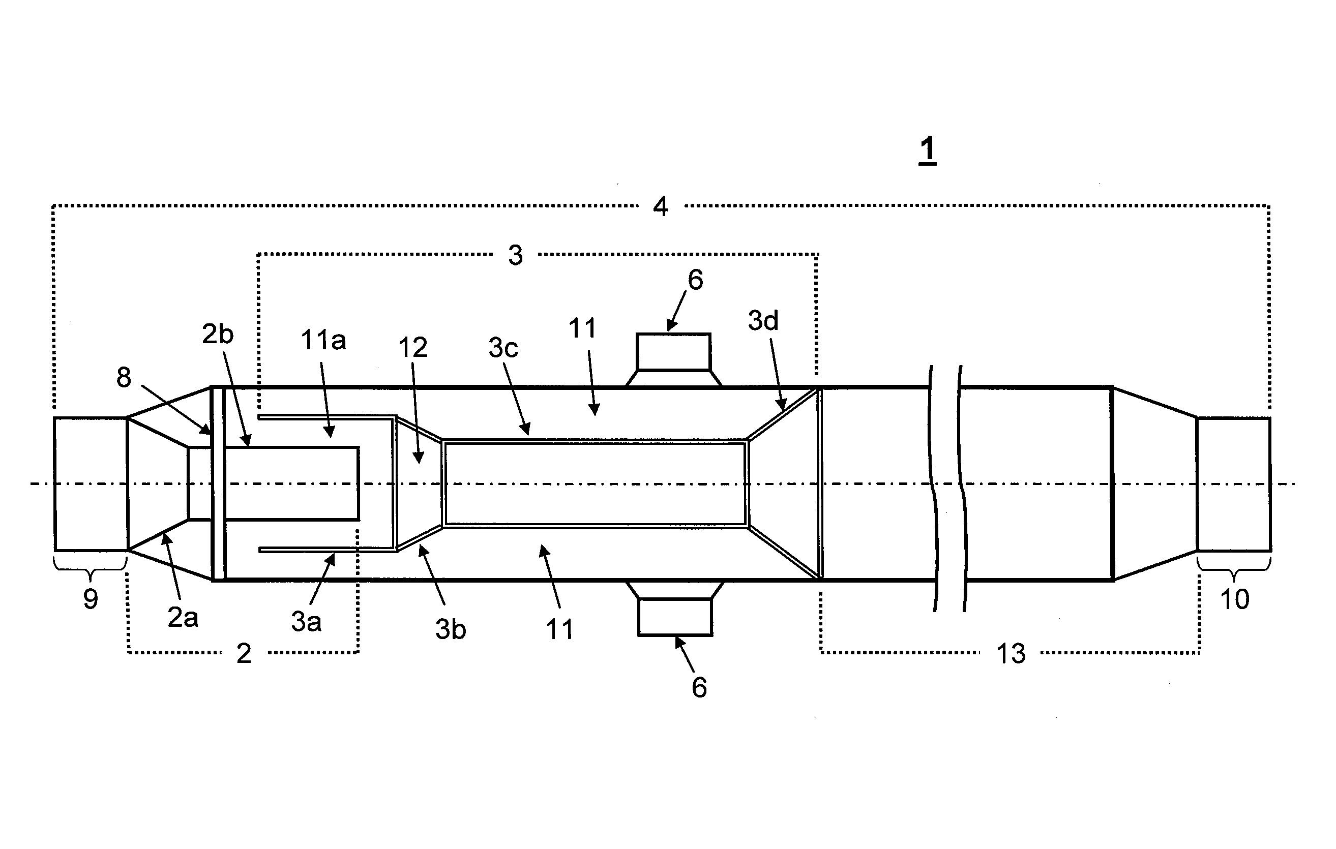
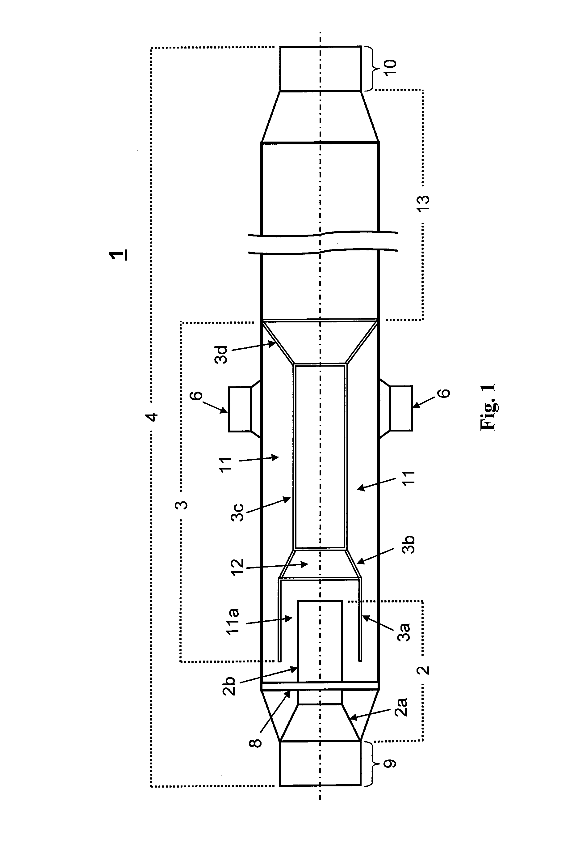
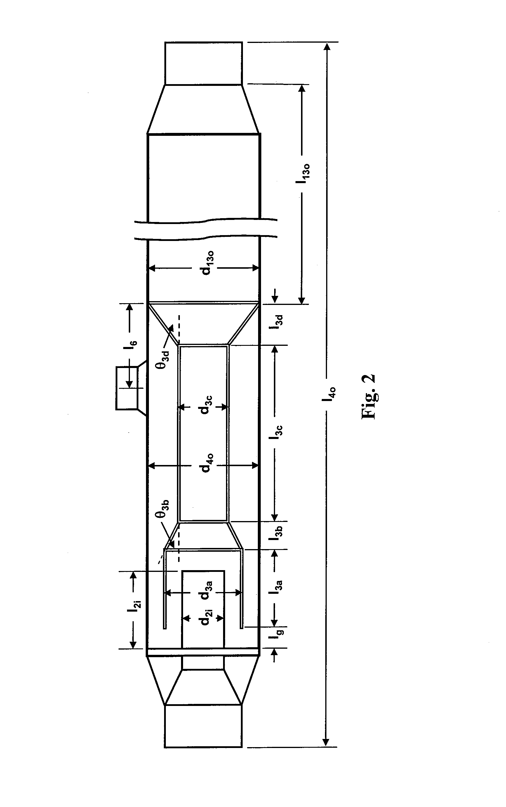
[0041]In one embodiment, the present invention relates to an improved heavy feed mixer (1) as presented in FIG. 1. The heavy feed mixer (1) may be located within the convection section of or external to the furnace and in fluid communication with the convection section of a conventional pyrolysis furnace and is designed to accept a mixed two-phase liquid-vapor mixture comprised of hydrocarbon feedstock and dilution steam. After the mixture passes through the heavy feed mixer (1), a substantially fully / completely vaporized stream of hydrocarbon feedstock is output and delivered to the radiant heating section for pyrolytic cr...


PUM

PropertyMeasurementUnit
angleaaaaaaaaaa
temperaturesaaaaaaaaaa
boiling pointaaaaaaaaaa

Abstract

An apparatus designed to completely vaporize an intake of heavy hydrocarbon feedstock is described. The apparatus, a so-called heavy feed mixer, is comprised of pipes being disposed coaxially about a common longitudinal axis. The inner tubular section delivers a two-phase liquid-vapor mixture of hydrocarbon feedstock and dilution steam to the apparatus. The converging / diverging tubular section has a unique structure which converges to a throat section and then diverges to an outlet section. The converging section directs a uniform shroud of superheated steam onto the hydrocarbon stream delivered by the inner tubular section. Impingement of the superheated steam with the intake stream initiates mixing and further vaporization within the throat section. The mixture traverses the converging / diverging tubular section and passes into the outlet section where vaporization is complete. The completely vaporized stream is directed out of the apparatus for further processing downstream.

Description

BACKGROUND OF THE INVENTION[0001]I. Field of the Invention[0002]This invention relates generally to an apparatus and process for vaporizing heavy hydrocarbon feedstock. In particular, the present invention relates to an apparatus and process for substantially completely vaporizing heavy hydrocarbon feedstock mixed with steam. The invention also relates to the use of the apparatus and process in the production of gaseous and liquid products such as olefins from heavy hydrocarbon feedstock.[0003]II. Background of the Related Art[0004]Thermal cracking to convert hydrocarbon feedstocks into more useful gaseous and liquid by-products is a well known process. The cracking process, which is also known as pyrolysis, cracks the carbon-carbon bonds in longer hydrocarbons to form smaller chain hydrocarbons. The overall reaction rate and end products are dependent on the processing temperature, pressure and residence time. Thermal cracking has commonly been used to produce olefins such as ethyl...

Claims


Application Information

Patent Timeline
Patent Type & Authority Patents(United States)
IPC IPC(8): C10G9/18
CPCC10G9/40C10G9/14B01D1/14C10G2300/1033B01B1/06C10G2300/807C10G2300/1074C10G2400/20
Inventor LARSON, WILLIAM ARTHURDABNEY, JR., GEORGE E.MURPHEY, III, JOHN R.FEWEL, JR., KENNETH JACKWANG, YONG
Owner STONE & WEBSTER PROCESS TECH
Learn More