
Device for managing termination of conductors with jack modules

a technology for managing jack modules and twisted conductors, which is applied in the direction of insulated conductors, coupling device connections, cables, etc., can solve the problems of requiring category 6 performance levels, being much more sensitive to variations in twisted pair termination and routing, and facilitating termination of twisted pair conductors. , the effect of less variation in electrical performan

Active Publication Date: 2008-07-08
COMMSCOPE INC
View PDF18 Cites 3 Cited by
  • Summary
  • Abstract
  • Description
  • Claims
  • Application Information

AI Technical Summary

Benefits of technology

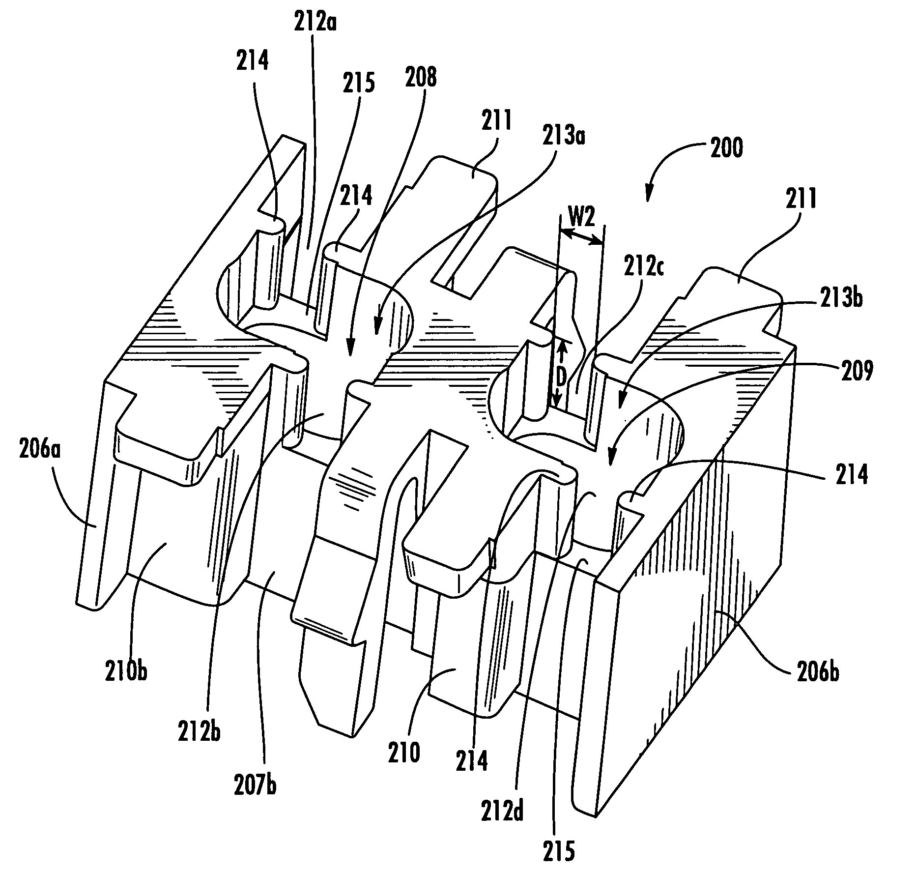
The present invention provides a device for organizing twisted pairs of conductors from a cable with a plurality of twisted pairs of conductors. This device can facilitate termination of twisted pair conductors onto IDCs or the like and can provide a termination with less dimensional variation (and, in turn, less variation in electrical performance) than prior termination devices. Additionally, the invention provides a communication connection system comprising a jack module with a plurality of IDCs, a communications cable comprising a plurality of twisted pairs of conductors, and a device for organizing the twisted pairs of conductors. The device is attached to the jack module, and each of the conductors is received in a respective one of the IDC slots. The method of interconnecting a communications cable with a jack module involves inserting the plurality of twisted pairs into the at least one aperture from above and securing each of the twisted pairs in a respective slot.

Problems solved by technology

However, recent developments, such as patch panels requiring category 6 performance levels, are much more sensitive to variations in twisted pair termination and routing.

Method used


Image

  • Device for managing termination of conductors with jack modules
  • Device for managing termination of conductors with jack modules
  • Device for managing termination of conductors with jack modules

Examples


Embodiment Construction

[0025]The present invention will be described more particularly hereinafter with reference to the accompanying drawings. The invention is not intended to be limited to the illustrated embodiments; rather, these embodiments are intended to fully and completely disclose the invention to those skilled in this art. In the drawings, like numbers refer to like elements throughout. Thicknesses and dimensions of some components may be exaggerated for clarity.

[0026]Unless otherwise defined, all terms (including technical and scientific terms) used herein have the same meaning as commonly understood by one of ordinary skill in the art to which this invention belongs. It will be further understood that terms, such as those defined in commonly used dictionaries, should be interpreted as having a meaning that is consistent with their meaning in the context of the relevant art and will not be interpreted in an idealized or overly formal sense unless expressly so defined herein.

[0027]In addition, ...


PUM

PropertyMeasurementUnit
widthaaaaaaaaaa
widthaaaaaaaaaa
lengthaaaaaaaaaa

Abstract

A device for receiving and organizing twisted pairs of conductors from a cable having a plurality of twisted pairs of conductors includes a block with upper and lower surfaces, first and second opposing end walls that define a longitudinal axis, and first and second opposing side walls. The block further comprises at least one aperture extending from the upper surface toward the lower surface, the aperture being sized and configured to receive each of the plurality of twisted pairs of a cable. Each of the side walls includes at least one open-ended slot opening downwardly, each of the slots being sized and configured to receive a respective twisted pair of conductors. In this configuration, the device can facilitate termination of twisted pair conductors onto IDCs or the like and can provide a termination with less dimensional variation (and, in turn, less variation in electrical performance) than prior termination devices.

Description

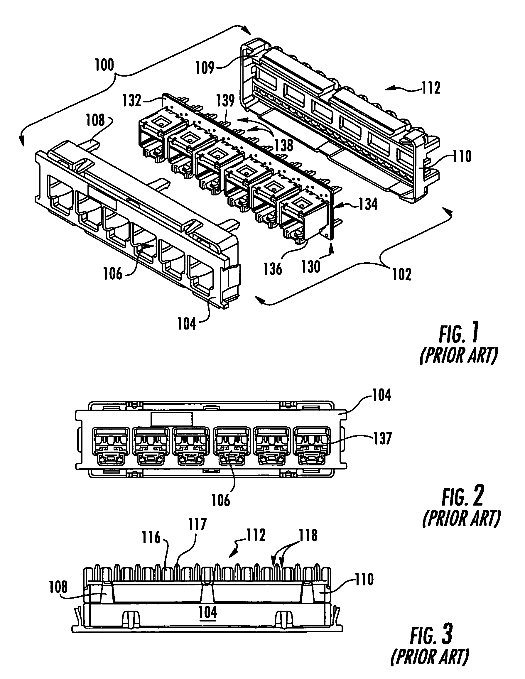
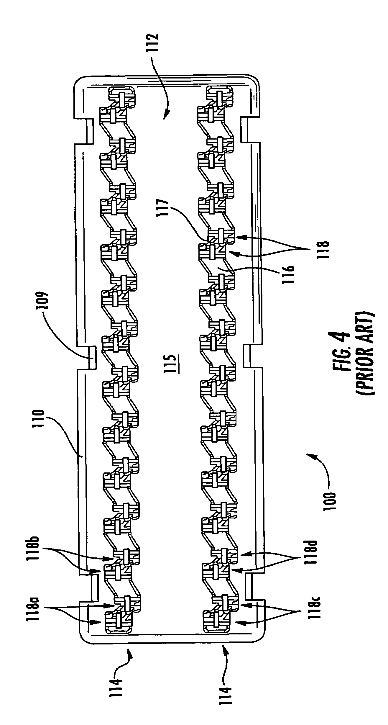
RELATED APPLICATION[0001]This application claims priority from U.S. Provisional Patent Application Ser. No. 60 / 757,643, filed Jan. 10, 2006 and entitled TERMINATION MANAGER, the disclosure of which is hereby incorporated herein in its entirety.FIELD OF THE INVENTION[0002]The present invention generally relates to routing twisted conductor pairs of a cable to a jack module and, in particular, to devices, systems and methods for controlling the consistency with which the twisted conductor pairs are routed.BACKGROUND OF THE INVENTION[0003]As is known, communications patch panels frequently incorporate the use of jack modules, like that shown at 100 in FIG. 1, that can be readily attached to and removed from the patch panel. Typically, existing jack modules 100 include a housing 102 having a front portion 104 and a back portion 110. The front portion 104 is visible to the user of the patch panel and includes one or more jack openings 106 configured to receive a communication connector (...

Claims


Application Information

Patent Timeline
Patent Type & Authority Patents(United States)
IPC IPC(8): H01B7/00
CPCH01R13/6463
Inventor MILLER, TIMOTHY C.LONG, TROY J.SATTERTHWAITE, DANNY L.
Owner COMMSCOPE INC
Learn More