Subsea termination gland, connector front end and connector assembly

a termination gland and connector technology, applied in the direction of cable termination, connection contact member material, cable connection connection, etc., can solve the problems of low insulation resistance, partial discharge, and low insulation resistance, so as to improve the quality of termination of such electrical conductors, improve the quality of termination, and reduce costs and time

Active Publication Date: 2019-09-24
SIEMENS ENERGY GLOBAL GMBH & CO KG
View PDF26 Cites 0 Cited by
  • Summary
  • Abstract
  • Description
  • Claims
  • Application Information

AI Technical Summary

Benefits of technology

[0008]Accordingly, there is a need to improve the termination of such electrical conductor for providing a subsea electrical connection. In particular, it is desirable to improve the quality of such termination with respect to the electrical insulation and reliability, and to reduce the costs and time required to make such termination. Furthermore, it is desirable to facilitate an onsite termination of such electrical conductor.

Problems solved by technology

Such filling has to occur with high precision in a clean environment, since any pollution of the filling fluid may lead to problems with respect to the insulation.
Any failures can result in a low insulation resistance, partial discharges, and at worst in an electrical breakdown of the insulators.
It may thus take several attempts before a sufficient quality of the fluid fill is achieved.
Furthermore, the fluid fill can take a relatively long time to perform, and additional time is required for curing.
If the first fluid fill was not successful, additional long times are required to strip down the connector and to have a further attempt.
The reason is that the pin may for example be required to close and seal a relatively large subsea enclosure that cannot easily be transported to the manufacturing site of the subsea cable.
Furthermore, such transportation would require a significant amount of time, and it may not have been decided on the configuration of cables and connectors which are to be used with the respective subsea device.
Accordingly, in such onsite environments, the cleanliness and the quality of the fluid fill of the termination gland is difficult to control, and pollution and an insufficient quality of the fill can result.
Furthermore, due to the required time for the fill, the filling of such connector requires resources and is cost intensive.

Method used


Image

  • Subsea termination gland, connector front end and connector assembly
  • Subsea termination gland, connector front end and connector assembly
  • Subsea termination gland, connector front end and connector assembly

Examples


Embodiment Construction

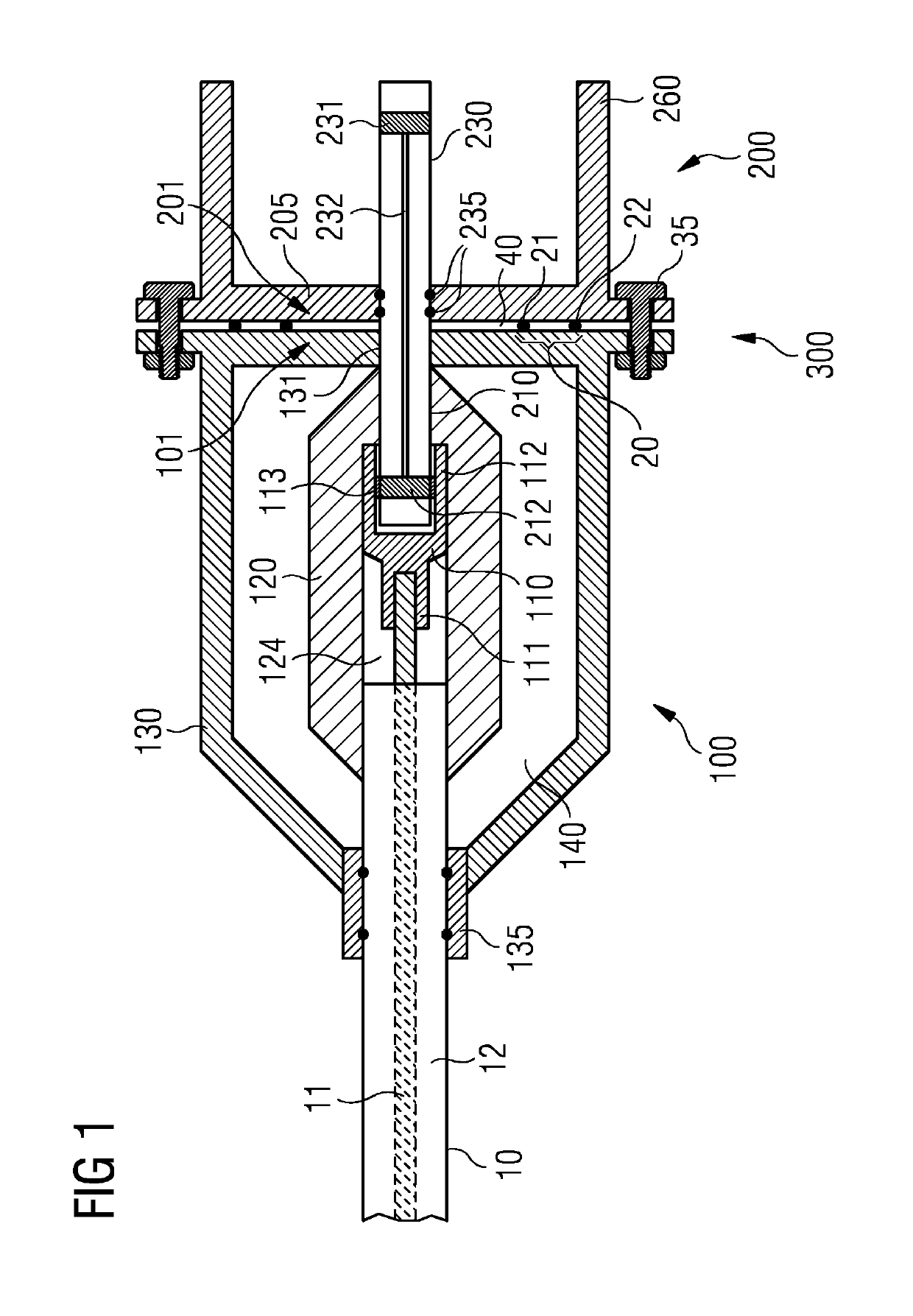
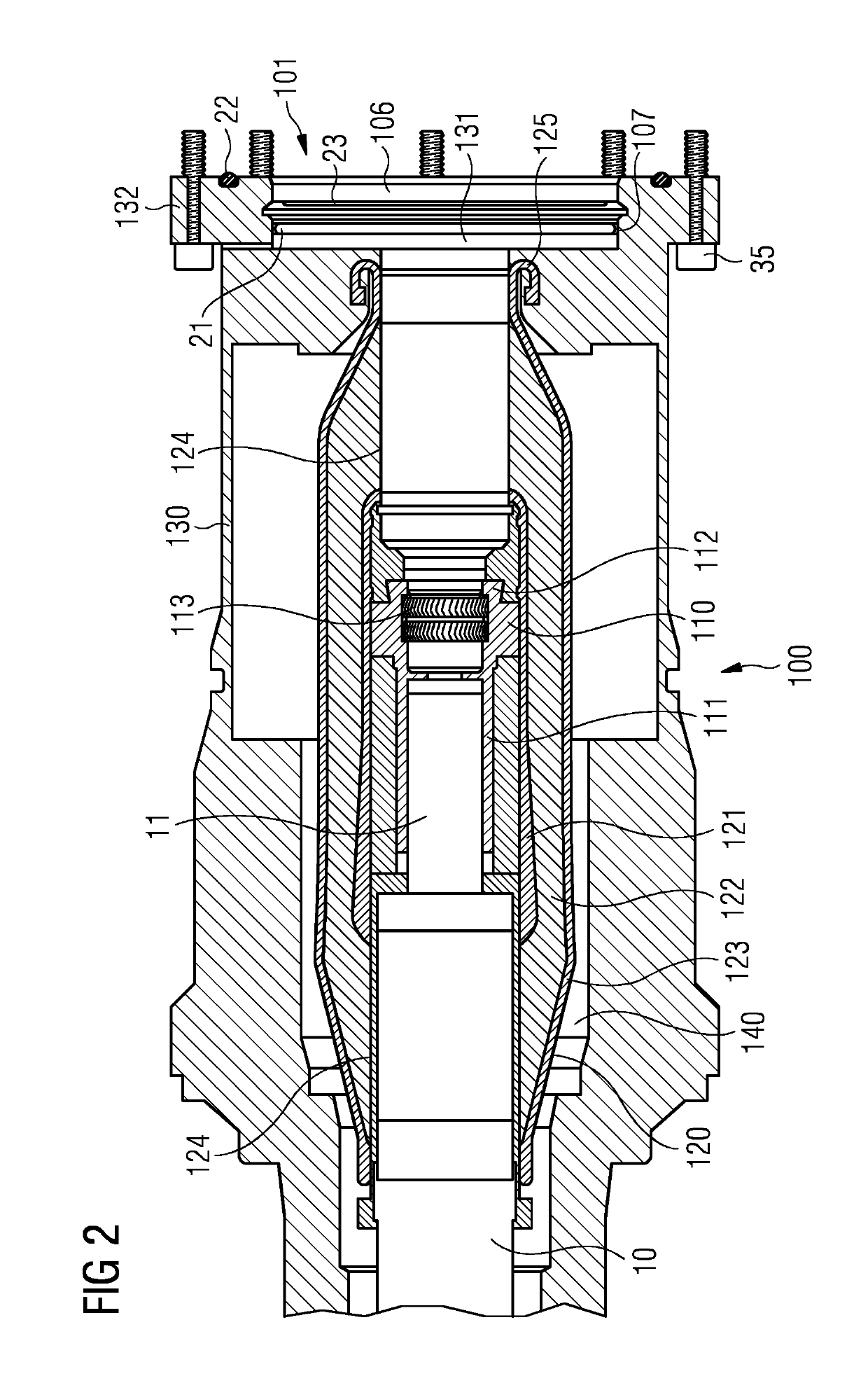
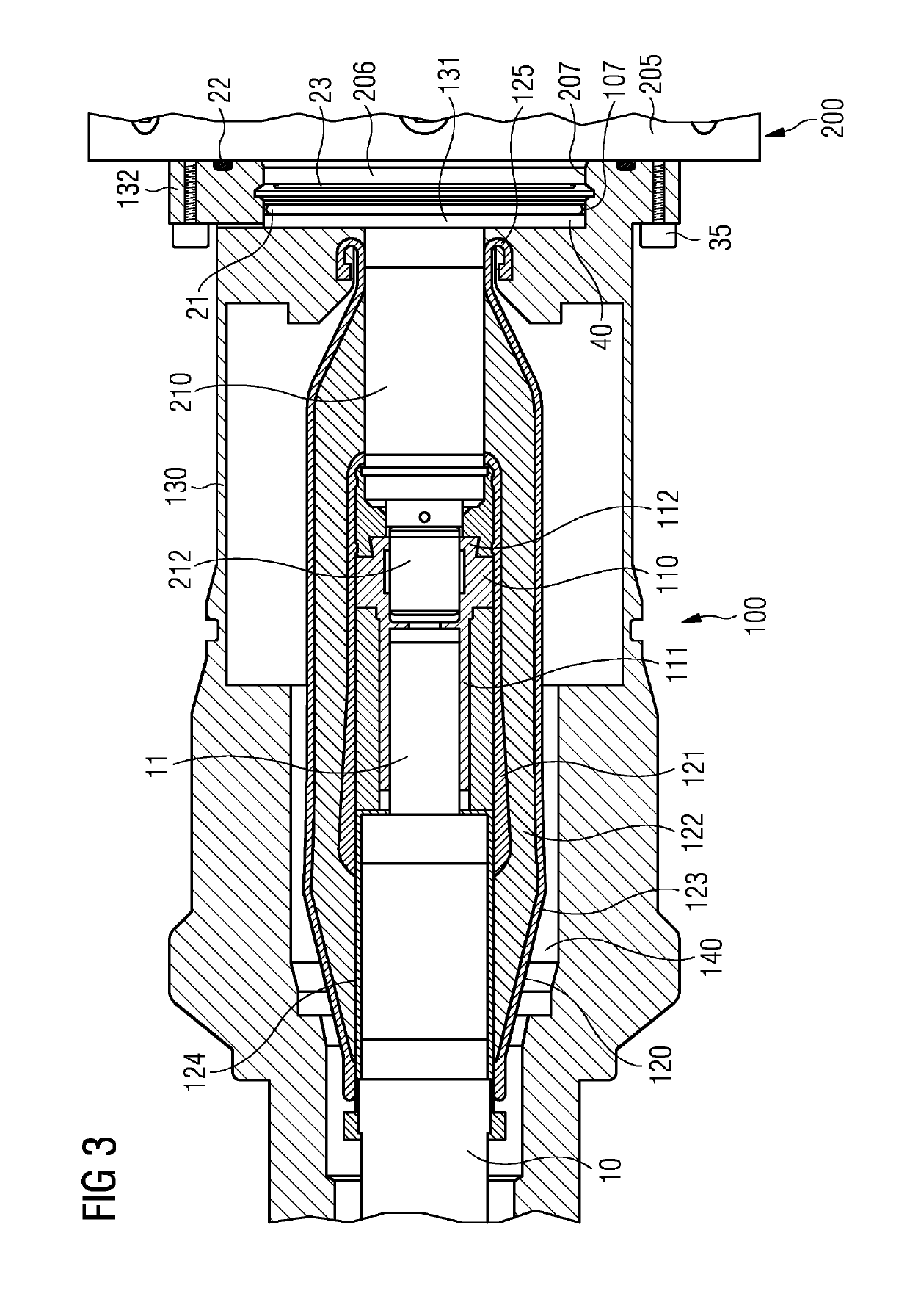
[0059]In the following, embodiments illustrated in the accompanying drawings are described in more detail. It should be clear that the following descriptions are only illustrative and non-restrictive. The drawings are only schematic representations, and elements in the drawings are not necessarily to scale with each other. In some embodiments, the elements illustrated in the drawings, for example of FIGS. 2 to 4 and 6 to 10, may be to scale with each other as shown in these drawings.

[0060]Conventionally, cable terminations have been crimped onto a cable with a standard crimp and the crimped cable is pushed home against the front end before a gland is built up around the cable to keep out water. Primary electrical insulation is provided by potting in a dielectric medium, usually silicone rubber. It is necessary to wait for the rubber to cure and then to fill the compensating fluid chambers. This may take several days.

[0061]By contrast, a dry mateable termination is one that can be te...


PUM


Abstract

A subsea termination gland for providing a termination and connection to an electrical conductor has a first connector interface which is dry-mateable and is configured to be mated with a complementary second connector interface of a connector front end. The termination gland further includes a termination assembly having a connection member which provides a first connection section of the first connector interface. The connection member is connectable to the electrical conductor. The first connection section is exposed to the ambient environment when determination gland is not mated with the connector front end. A sealing section seals the termination gland to the connector front end.

Description

CROSS REFERENCE TO RELATED APPLICATIONS[0001]This application is the US National Stage of International Application No. PCT / EP2017 / 051558 filed Jan. 25, 2017, and claims the benefit thereof. The International Application claims the benefit of European Application No. EP16153846 filed Feb. 2, 2016. All of the applications are incorporated by reference herein in their entirety.FIELD OF INVENTION[0002]The present invention relates to a subsea termination gland for providing a termination and connection to an electrical conductor in an underwater environment, to a connector front end for underwater use and to a connector assembly for underwater use that comprises such termination gland and connector front end.BACKGROUND OF INVENTION[0003]Several applications are known in which connections need to be provided underwater, such as electrical connections or optical connections. Examples include a subsea installation for the production of hydrocarbons from a subsea well, in which different c...

Claims


Application Information

Patent Timeline
Patent Type & Authority Patents(United States)
IPC IPC(8): H01R4/60H02G15/14H01R13/52H02G15/06H01R13/523H02G1/10
CPCH02G15/14H02G15/06H01R13/523H02G1/10H01R13/5208
Inventor LEWIN, RICHARDPLANT, CHRISTOPHER
Owner SIEMENS ENERGY GLOBAL GMBH & CO KG
Why Eureka
Try Eureka