
Real time averaged impedance calibration for on-die termination

a real-time averaged impedance and on-die termination technology, applied in the field of data transmission, can solve the problems of increasing the bit error rate of data transmission, affecting the accuracy of data transmission, and the level of transmission and receiving signals can be distorted, so as to improve the accuracy and reduce the area used. , the effect of improving the accuracy

Active Publication Date: 2013-02-26
ATI TECH INC
View PDF14 Cites 6 Cited by
  • Summary
  • Abstract
  • Description
  • Claims
  • Application Information

AI Technical Summary

Benefits of technology

The invention provides a better way to calibrate the speed of data transmission in computer chips. By averaging the results from multiple measurements, the technique is more accurate than previous methods without adding extra detail. This can lead to more precise data transmission and better efficiency in chip design.

Problems solved by technology

Without proper impedance matching between a transmitter and a receiver, levels of transmission and receiving signals can be distorted due to reflected waves, and as a result, the bit error rate of data transmission increases.
Variations in the fabrication process as well as fluctuations in voltage and temperature result in variability in the resistive characteristics of the ODT elements.
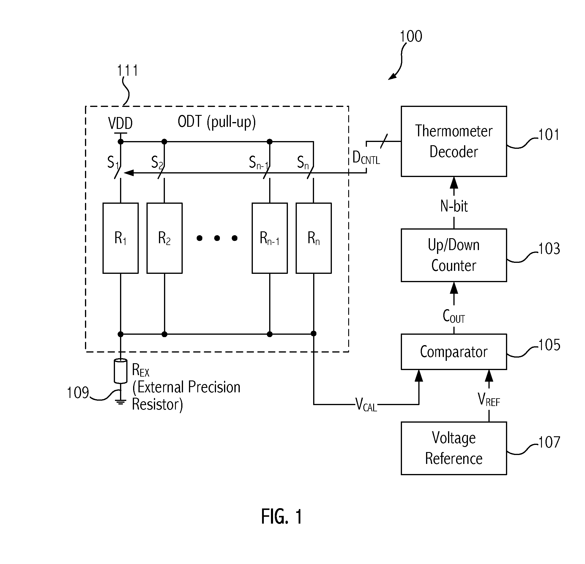
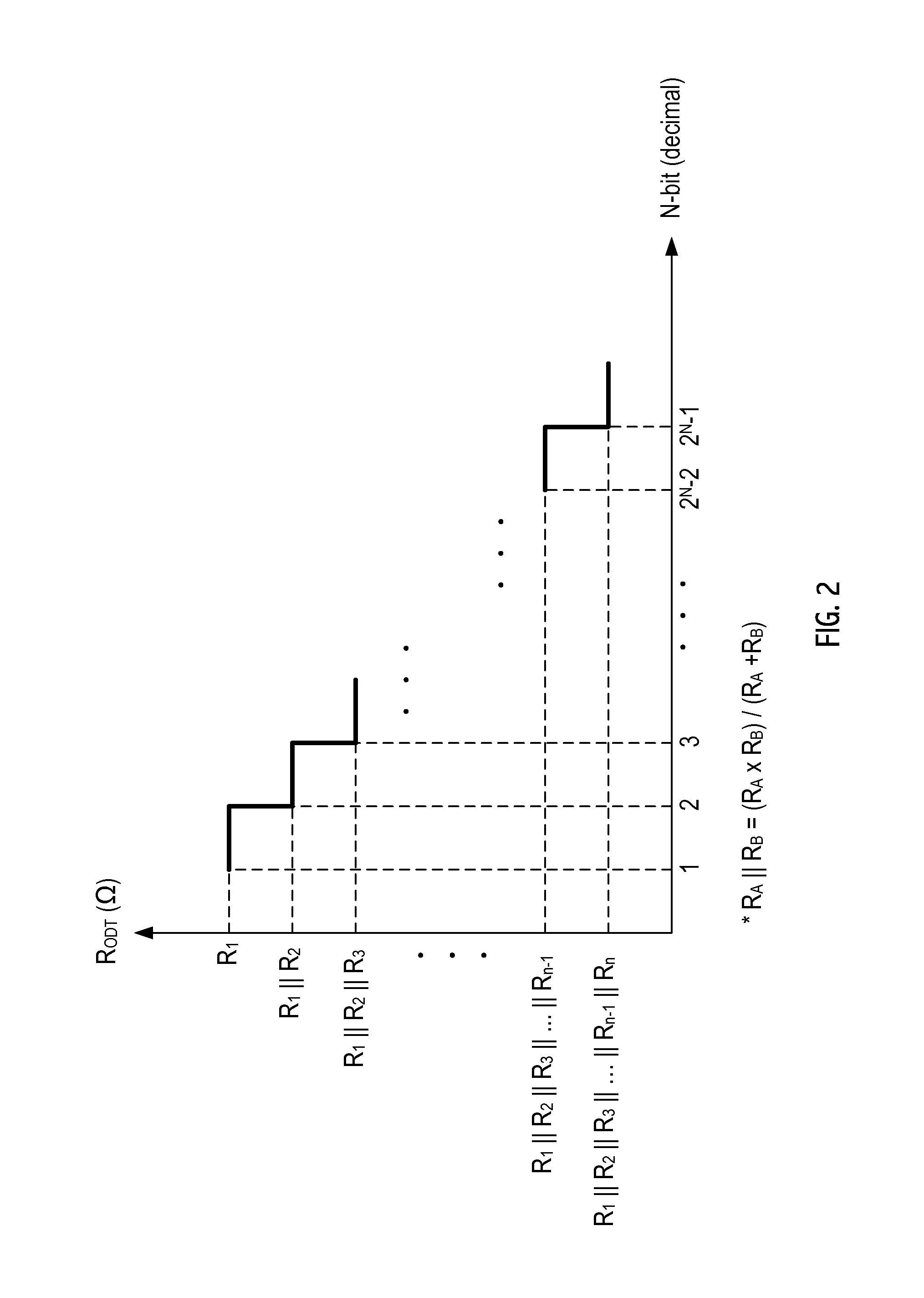
If the state of COUT is not changed until the up / down counter counts down to 0 or up to 2N−1, it means that RODT is not able to achieve the target impedance with the proper accuracy.

Method used


Image

  • Real time averaged impedance calibration for on-die termination
  • Real time averaged impedance calibration for on-die termination
  • Real time averaged impedance calibration for on-die termination

Examples


Embodiment Construction

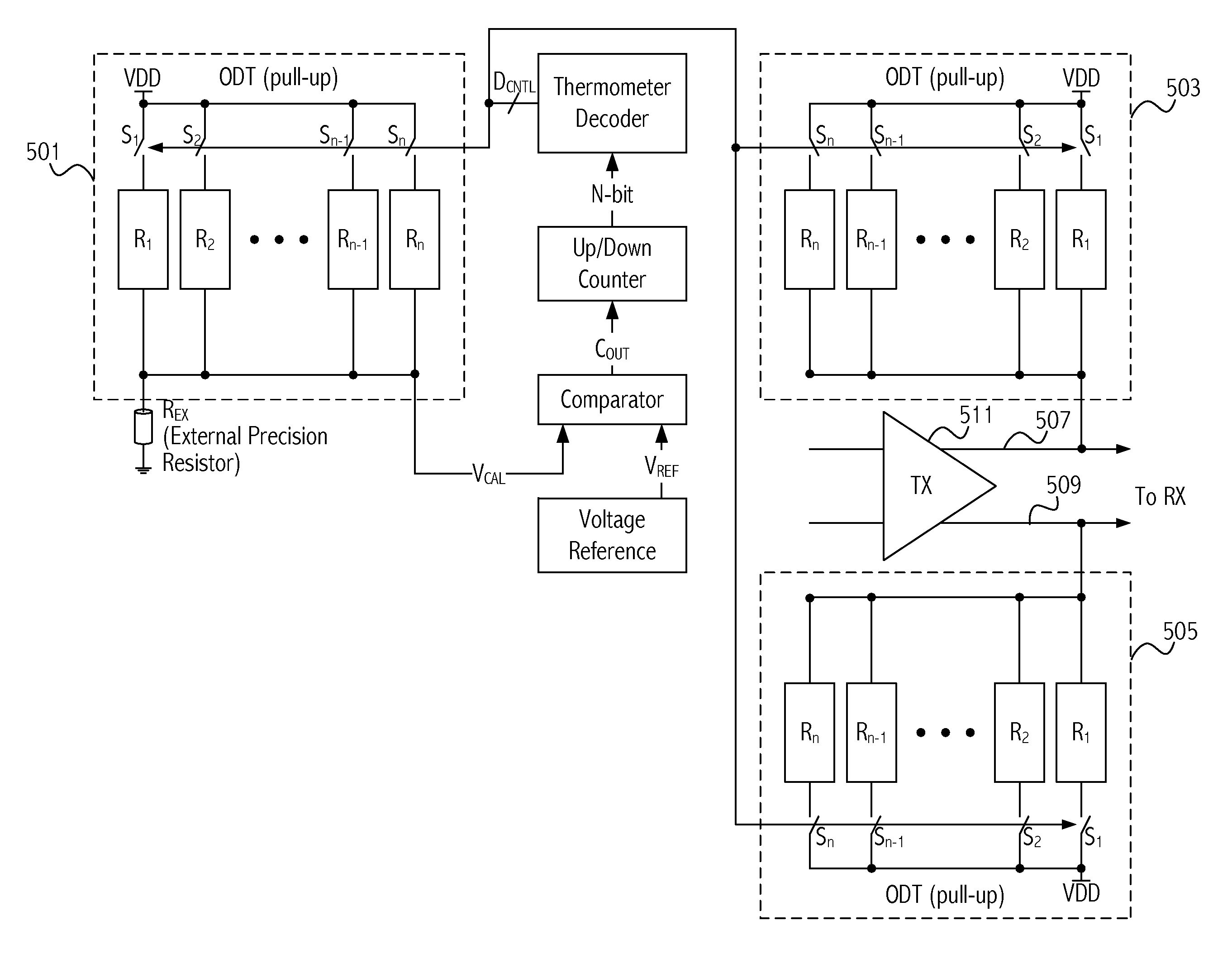
[0018]Improvements in on-die termination can lead to greater accuracy, smaller area utilized, and less toggling. Embodiments of the invention provide an impedance calibration technique for on-die termination (ODT) with better accuracy than prior approaches without increasing resolution by utilizing an averaging impedance technique.

[0019]In one embodiment, a method is provided for a calibrated termination impedance that includes supplying first and second control signals having different values to configure respectively first and second switch arrays and associated first and second resistive loads coupled in parallel. Each of the resistive loads has their respective resistance values determined by configuration of the switch arrays. The first control signals cause the first resistive load to have a first resistance value and the second control signals cause the second resistive load to have a second resistance value that differs from the first resistance value. In embodiments, the fi...


PUM


Abstract

An averaged impedance calibration is obtained by utilizing two separately controlled resistive loads arranged in parallel and choosing two adjacent control codes to configure switch arrays to set the resistance of each of the separate resistive loads. The resistance of the resistive loads is averaged to provide greater accuracy. The two adjacent control codes are close to the target impedance value and typically one is slightly higher and one is slightly lower than the target impedance value.

Description

BACKGROUND[0001]1. Field of the Invention[0002]This invention relates to data transmission and more particularly to on-die termination associated therewith.[0003]2. Description of the Related Art[0004]High-speed serial data transmission systems are being adopted to overcome limitations of data transmission rates of conventional parallel data transmission systems. Typically, a serial data transmission system utilizes a differential signal structure to increase noise immunity. In such a serial data interface, impedance calibration between a transmitter and a receiver is important. Without proper impedance matching between a transmitter and a receiver, levels of transmission and receiving signals can be distorted due to reflected waves, and as a result, the bit error rate of data transmission increases.[0005]As the performance requirements of serial data transmission systems continue to increase, there are increasing requirements to deliver signal integrity that enables reliable operat...

Claims


Application Information

Patent Timeline
Patent Type & Authority Patents(United States)
IPC IPC(8): H03K17/16
CPCH03K19/017545H03K19/017581H04L25/0278
Inventor CHO, JUNHO J. H.
Owner ATI TECH INC
Learn More