Preterminated fiber optic connector sub-assemblies, and related fiber optic connectors, cable assemblies, and methods

a fiber optic connector and pretermination technology, applied in the direction of optics, instruments, optical light guides, etc., can solve the problems of reducing the throughput of processing fiber optic connector termination, affecting quality, and providing cost in the termination process, so as to improve the quality of the termination process, reduce the risk of discovering a flaw, and enhance the effect of optical termination

Active Publication Date: 2015-06-09
CORNING OPTICAL COMM LLC
View PDF194 Cites 5 Cited by
  • Summary
  • Abstract
  • Description
  • Claims
  • Application Information

AI Technical Summary

Benefits of technology

[0009]Providing a pre-terminated fiber optic sub-assembly that includes an optical fiber stub that can be fusion spliced within a ferrule bore of a ferrule, wherein the optical fiber stub is not directly accessible through the ferrule body outside of the ferrule bore openings, may be advantageous. As a non-limiting example, fusion splicing may provide an enhanced optical termination over mechanical splicing. Further, as another example, by providing a ferrule that has properties to allow thermal energy to be directed through the ferrule body into the ferrule bore of the ferrule, a fiber access opening or port beyond the ferrule bore is not required to be provided in the ferrule body. Providing a fiber access opening or port in the ferrule would expose the optical fiber stub outside of the ferrule bore during splicing.
[0010]Further, providing a pre-terminated fiber optic sub-assembly that includes an optical fiber stub that can be fusion spliced within a ferrule bore of a ferrule can also allow highly automated fiber optic cable termination processes. As a non-limiting example, the pre-terminated fiber optic connector sub-assemblies disclosed herein can be assembled and prepared as a small and more easily automatable part, separately and independently from a fiber optic cable assembly. The pre-installed optical fiber stub extending from a front end of the ferrule of a pre-terminated fiber optic connector sub-assembly can be prepared and polished to provide an optical end face on the ferrule, before being terminated on a fiber optic cable. The entire fiber optic cable assembly does not have to accompany the pre-terminated fiber optic connector sub-assembly during its preparation and assembly. The assembled and prepared pre-terminated fiber optic connector sub-assemblies can then be distributed within a factory or in the field, to be used to terminate and connectorize a fiber optic cable.
[0011]Also as another non-limiting example, the pre-terminated fiber optic connector sub-assemblies disclosed herein, being capable of assembly and preparation independent of fiber optic cable assembly processes, allows the pre-terminated fiber optic connector sub-assemblies to be prepared to desired specifications independent of the fiber optic cable assembly processes or cable type. This may allow processes for assembly and preparation of pre-terminated fiber optic connector sub-assemblies to not be specific to or limited by specific fiber optic cable assembly processes and / or cable types. The pre-terminated fiber optic connector sub-assemblies disclosed herein can also be tested prior to termination on a fiber optic cable. Thus, pre-terminated fiber optic connector sub-assemblies discovered as having flaws requiring rework or scrapping, will not add delay in independent fiber optic cable sub-assembly processes. Also, testing prepared optical end faces of ferrules in pre-terminated fiber optic connector sub-assemblies prior to termination on a fiber optic cable can reduce the risk of discovering a flaw only after termination and risking scrapping an entire fiber optic cable assembly. Providing pre-terminated fiber optic connector sub-assemblies that can be fusion spliced within the ferrule bore may also allow improved termination efficiency of fiber optic cables by technicians in the field, because the pre-installed optical fiber stub and end face preparations can be performed prior to termination in a factory, according to highly automated and precise factory processes.

Problems solved by technology

The influence of manual labor in the termination process provides cost, affects quality, and can decrease throughput in processing fiber optic connector terminations.
Automated fiber optic connector termination processes for fiber optic cable preparations have been employed to reduce manual labor influence, but at significant capital costs.
Even so, these automated fiber optic connector terminations processes may not be flexible with respect to terminating varieties of fiber optic connectors or fiber optic cable types.
Further, with these fiber optic connector termination processes, if one fiber optic connector termination fails, it must be reworked or the entire fiber optic cable must scrapped.
In either case, the fiber optic cable assembly can be delayed, thereby disrupting fiber optic cable assembly throughput and increasing scrapped fiber optic cables, increasing costs as a result.

Method used


Image

  • Preterminated fiber optic connector sub-assemblies, and related fiber optic connectors, cable assemblies, and methods
  • Preterminated fiber optic connector sub-assemblies, and related fiber optic connectors, cable assemblies, and methods
  • Preterminated fiber optic connector sub-assemblies, and related fiber optic connectors, cable assemblies, and methods

Examples


Embodiment Construction

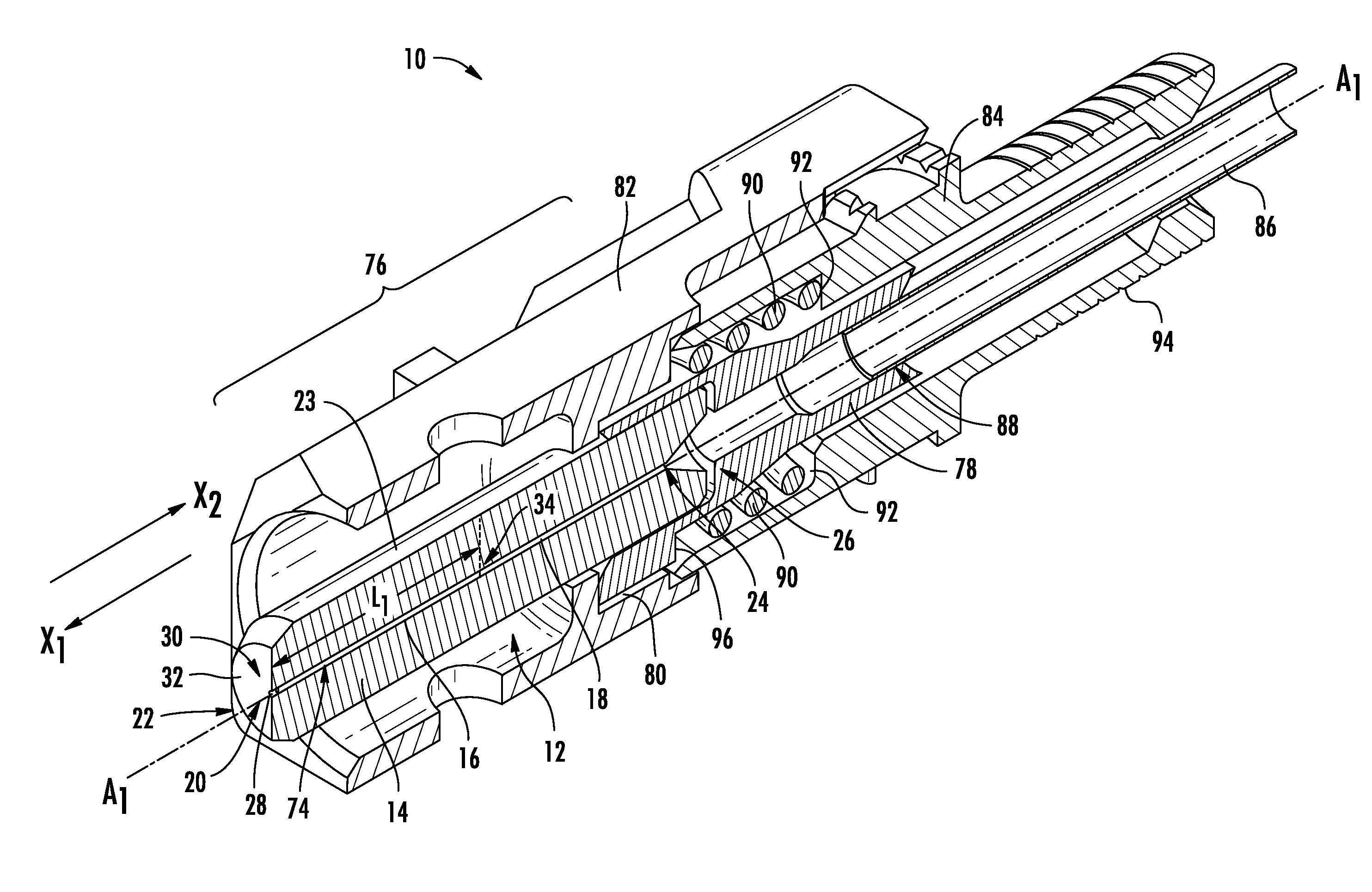
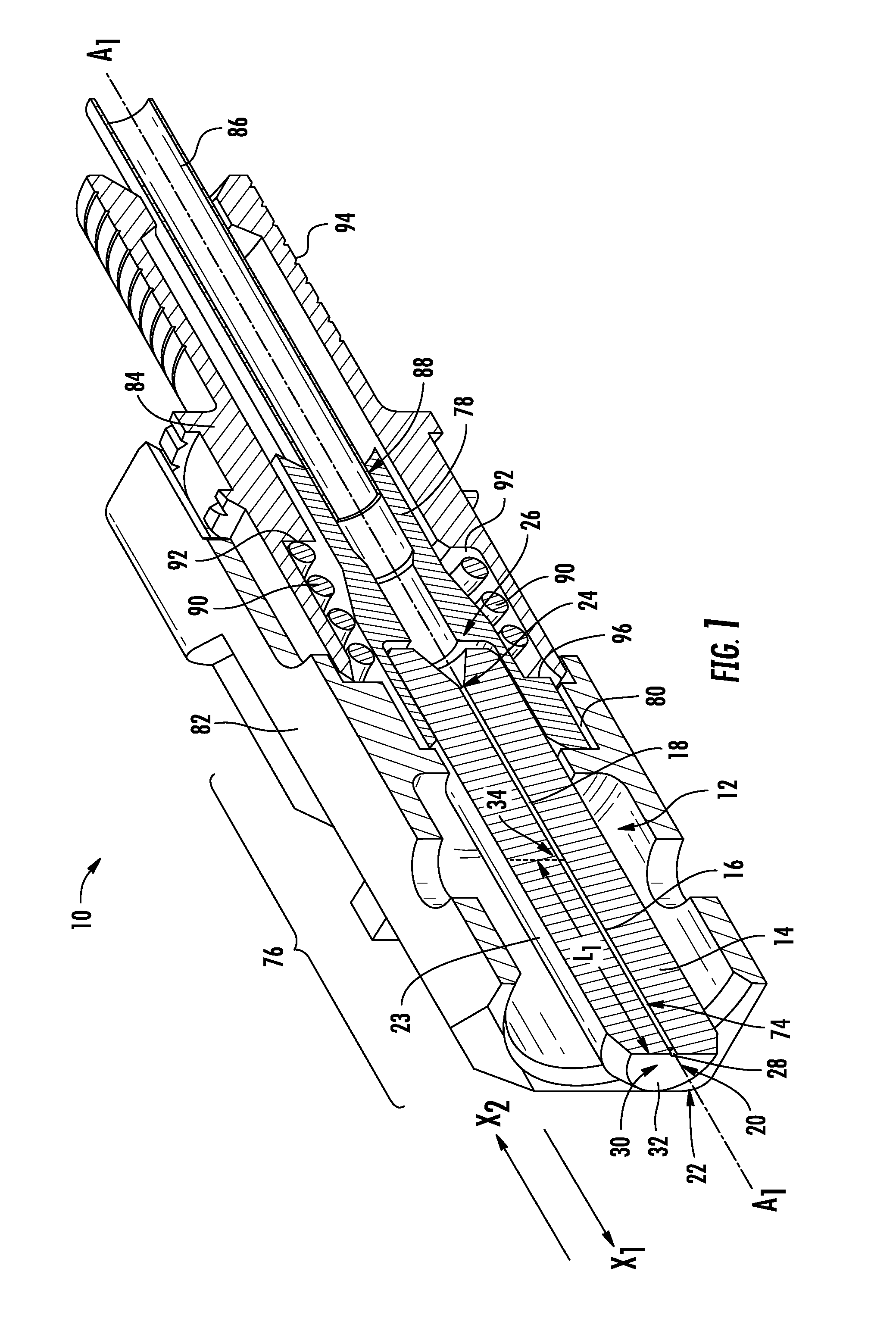
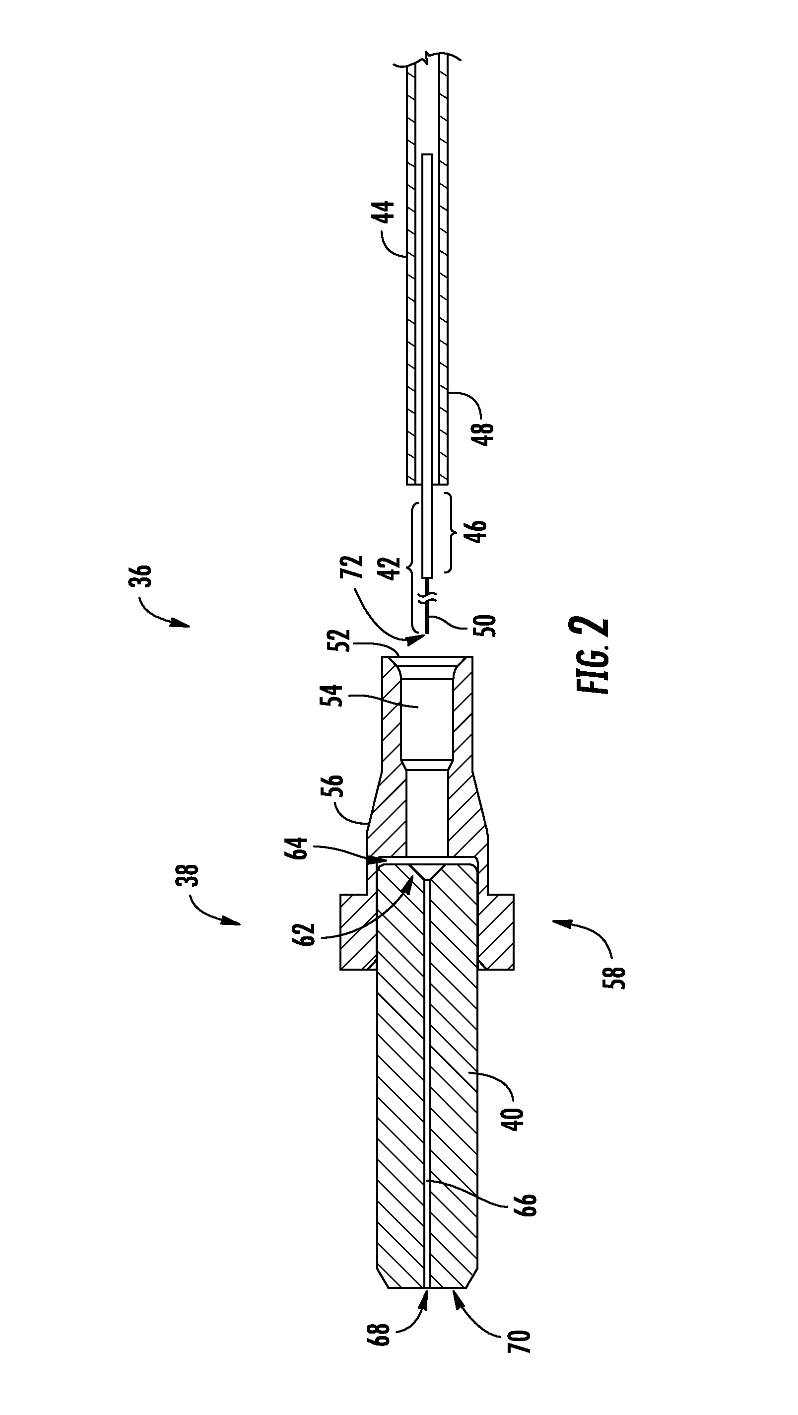
[0008]Embodiments disclosed herein include pre-terminated fiber optic connector sub-assemblies. Related fiber optic connectors, cable assemblies, and methods are also disclosed. In certain embodiments, an optical fiber stub is pre-installed in a ferrule bore (also known as a “micro-hole”) of the ferrule of a fiber optic connector sub-assembly, to provide the pre-terminated fiber optic connector sub-assembly. The optical fiber stub, which is shorter in length than the ferrule length, can be pre-installed in the ferrule bore of the ferrule, prior to termination of the fiber optic connector sub-assembly on a fiber optic cable. If the ferrule is a multi-fiber ferrule, multiple optical fiber stubs may be pre-installed in the ferrule. Because the pre-terminated optical fiber stub is not directly accessible through a ferrule body of the ferrule when a field optical fiber is disposed in the ferrule body to be fusion spliced with the optical fiber stub, the ferrule has properties that allow ...


PUM

PropertyMeasurementUnit
wavelength rangeaaaaaaaaaa
thickaaaaaaaaaa

Abstract

Embodiments disclosed herein include pre-terminated fiber optic connector sub-assemblies, and related fiber optic connectors, cables, and methods. In certain embodiments, an optical fiber stub is pre-installed in a ferrule bore of a ferrule of a fiber optic connector sub-assembly, to provide the pre-terminated fiber optic connector sub-assembly. The optical fiber stub can be pre-installed in the ferrule bore prior to termination of the fiber optic connector sub-assembly. Because the pre-terminated optical fiber stub disposed in the ferrule bore is not directly accessible through a ferrule body of the ferrule when a field optical fiber is disposed in the ferrule bore for fusion splicing, the ferrule has properties that allow thermal energy to be directed through the ferrule body into the ferrule bore. In this manner, the optical fiber stub pre-installed in the ferrule bore can be fusion spliced with the field optical fiber to terminate a fiber optic cable.

Description

BACKGROUND[0001]1. Field of the Disclosure[0002]The technology of the disclosure relates to termination of fiber optic connectors on optical fibers or fiber optic cables.[0003]2. Technical Background[0004]Benefits of utilizing optical fiber include extremely wide bandwidth and low noise operation. Because of these advantages, optical fiber is increasingly being used for a variety of applications, including but not limited to broadband voice, video, and data transmission in communications networks. As a result, communications networks include a number of optical interconnection points in fiber optic equipment and between fiber optic cables in which optical fibers must be interconnected via fiber optic connections. To conveniently provide these fiber optic connections, fiber optic connectors are provided. A fiber optic connector includes a housing that provides internal components for receiving, supporting, protecting, and aligning one or more end portions of optical fibers exposed fr...

Claims


Application Information

Patent Timeline
Patent Type & Authority Patents(United States)
IPC IPC(8): G02B6/36G02B6/38G02B6/255
CPCG02B6/3855G02B6/3846Y10T29/4989G02B6/2551G02B6/3861
Inventor BAUCO, ANTHONY SEBASTIANDANLEY, JEFFREY DEANELKINS, II, ROBERT BRUCEGREGORSKI, STEVEN JOSEPH
Owner CORNING OPTICAL COMM LLC
Why Eureka
Try Eureka