
Transmitting apparatus with source termination

a technology of source termination and transmitting device, which is applied in the field of data communication, can solve problems such as degrading the signal quality of the transmitting device, and achieve the effect of maintaining signal quality and reducing emi

Active Publication Date: 2018-01-16
LATTICE SEMICON CORP
View PDF92 Cites 2 Cited by
  • Summary
  • Abstract
  • Description
  • Claims
  • Application Information

AI Technical Summary

Benefits of technology

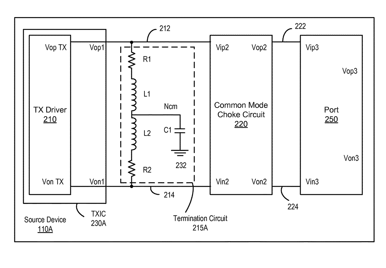
[0005]Embodiments of the present disclosure relate to a transmitting apparatus with an improved source termination for a chip to chip communication in a manner that properly terminates an output of the transmitter, maintains the signal quality, and reduces EMI.

Problems solved by technology

However, the common mode choke may degrade the signal quality from the transmitting device.

Method used


Image

  • Transmitting apparatus with source termination
  • Transmitting apparatus with source termination
  • Transmitting apparatus with source termination

Examples


Embodiment Construction

[0022]The Figures (FIG.) and the following description relate to various embodiments by way of illustration only. It should be noted that from the following discussion, alternative embodiments of the structures and methods disclosed herein will be readily recognized as viable alternatives that may be employed without departing from the principles discussed herein. Reference will now be made in detail to several embodiments, examples of which are illustrated in the accompanying figures. It is noted that wherever practicable similar or like reference numbers may be used in the figures and may indicate similar or like functionality.

[0023]As used herein, the term directly connected means that two components are directly connected to each other without any intervening components. The term coupled means that two components may be directly connected to each other or that intervening components may be located between two components.

[0024]Embodiments of the present disclosure include a trans...


PUM


Abstract

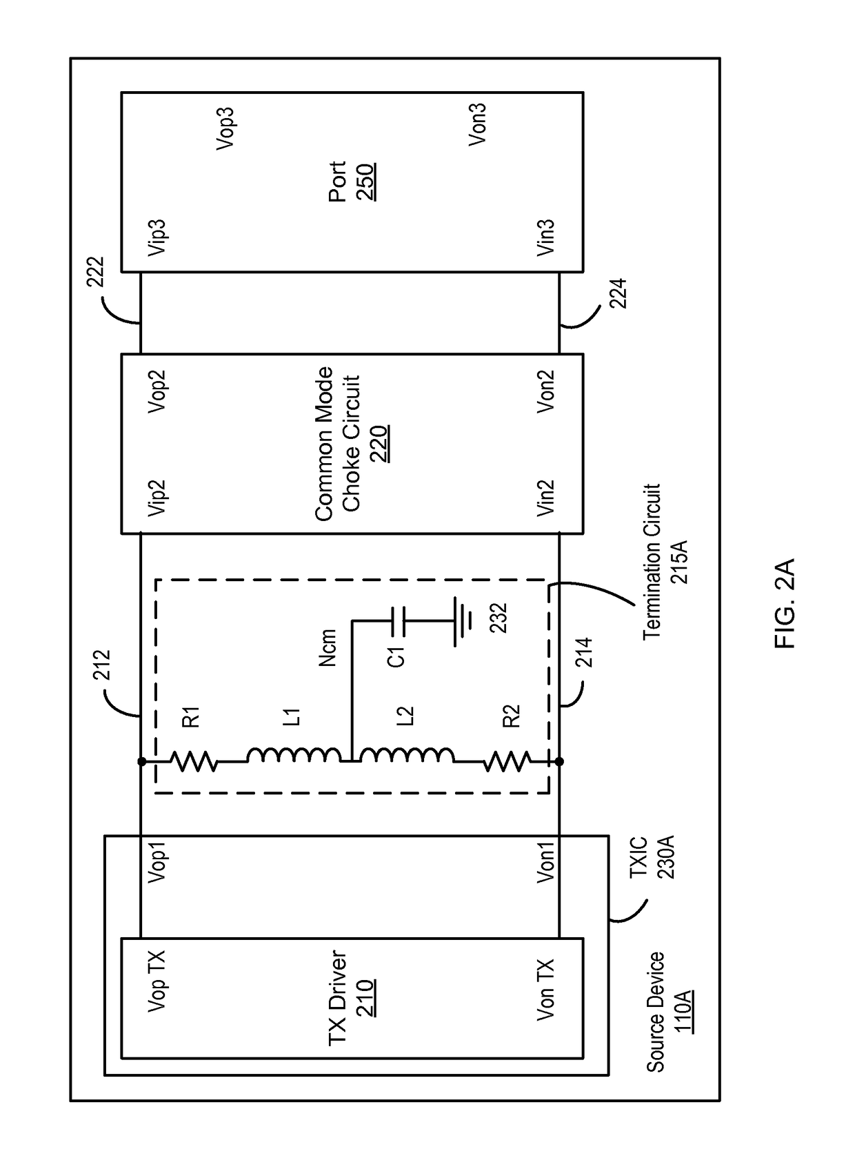
In one embodiment, an apparatus for transmitting a signal with an improved termination is disclosed. The apparatus includes a driver to generate a differential mode signal superimposed on a common mode signal at a differential driver output of the driver. The differential driver output includes a first driver output and a second driver output. The apparatus also includes a termination circuit coupled between the first driver output and the second driver output. The termination circuit includes a capacitor connected to a node. The termination circuit also includes a first resistor and a first inductive element coupled in series between the first driver output and the node. In addition, the termination circuit includes a second resistor and a second inductive element coupled in series between the second driver output and the node.

Description

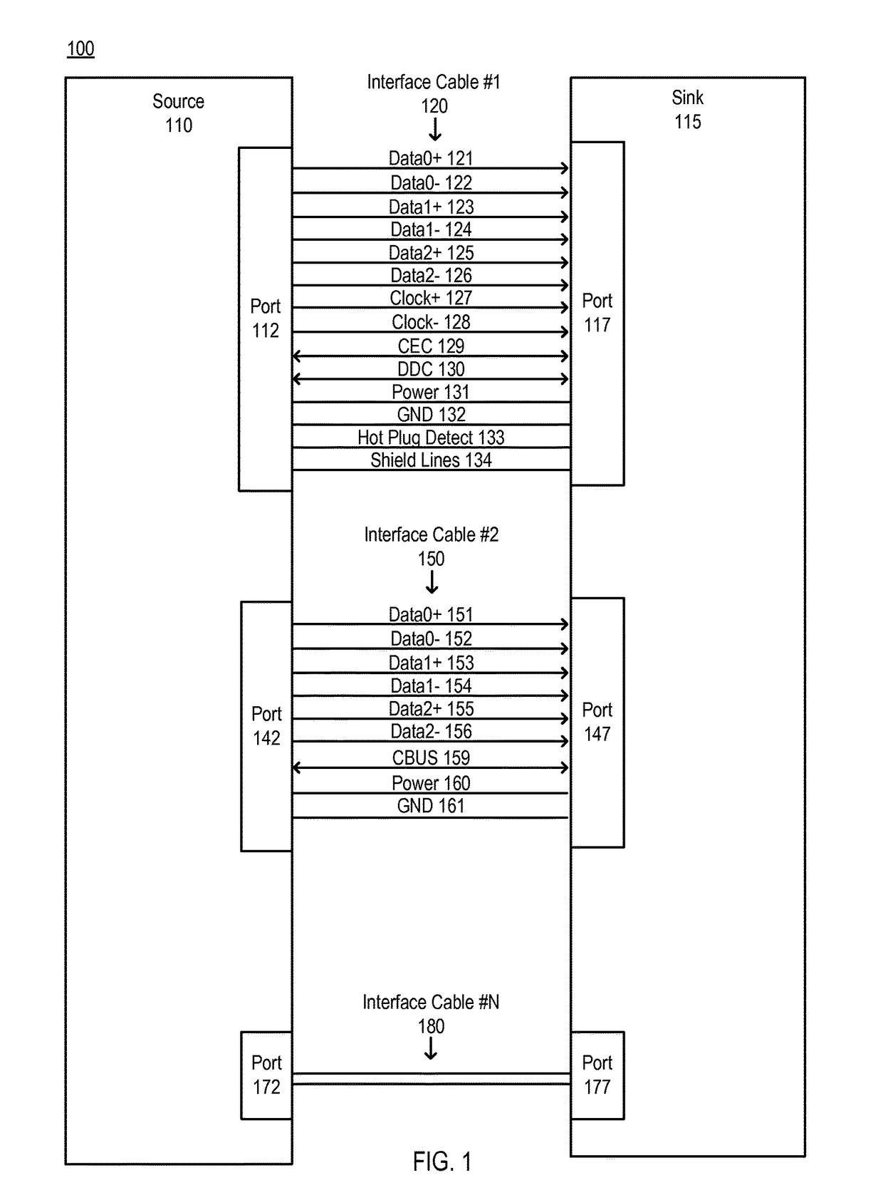
BACKGROUND[0001]1. Field of the Disclosure[0002]This disclosure pertains in general to data communications, and more specifically to signal integrity on a chip to chip communication.[0003]2. Description of the Related Art[0004]Video and audio data are typically transferred from one device to another across using communication links. In an advanced protocol such as the high definition multimedia interface (HDMI) or the mobile high definition link (MHL), one device may communicate with another using a common mode signal superimposed on a differential mode signal. The common mode signal may generate Electromagnetic Interference (EMI). To suppress the EMI and properly terminate the output of a transmitting device, a common mode choke may be employed between the two devices. However, the common mode choke may degrade the signal quality from the transmitting device.SUMMARY[0005]Embodiments of the present disclosure relate to a transmitting apparatus with an improved source termination for...

Claims


Application Information

Patent Timeline
Patent Type & Authority Patents(United States)
IPC IPC(8): H03K19/00H03K19/003
CPCH03K19/00346H03K19/0005
Inventor JEONG, YOUCHULLEE, JUNWOOLEE, INYEOLSUNG, BAEGIN
Owner LATTICE SEMICON CORP
Learn More