
Method of manufacturing a magnetic head

a manufacturing method and magnetic head technology, applied in the field of magnetic head, can solve the problems of long milling time, inability to consider the difficult scraping, etc., and achieve the effect of less dimensional variations of the track width

Inactive Publication Date: 2010-05-18
WESTERN DIGITAL TECH INC
View PDF9 Cites 4 Cited by
  • Summary
  • Abstract
  • Description
  • Claims
  • Application Information

AI Technical Summary

Benefits of technology

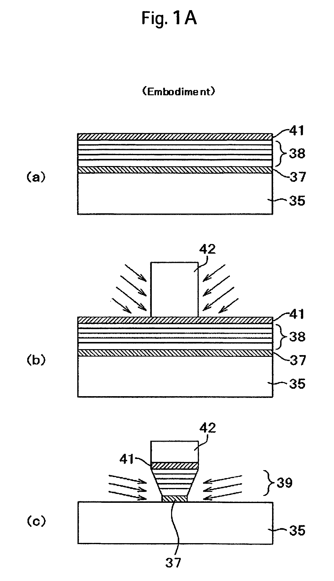
This approach allows for the formation of magnetic heads with less dimensional scattering in track width and improved recording magnetic field strength, while maintaining the inverted trapezoidal shape, enabling increased recording density and stability.

Problems solved by technology

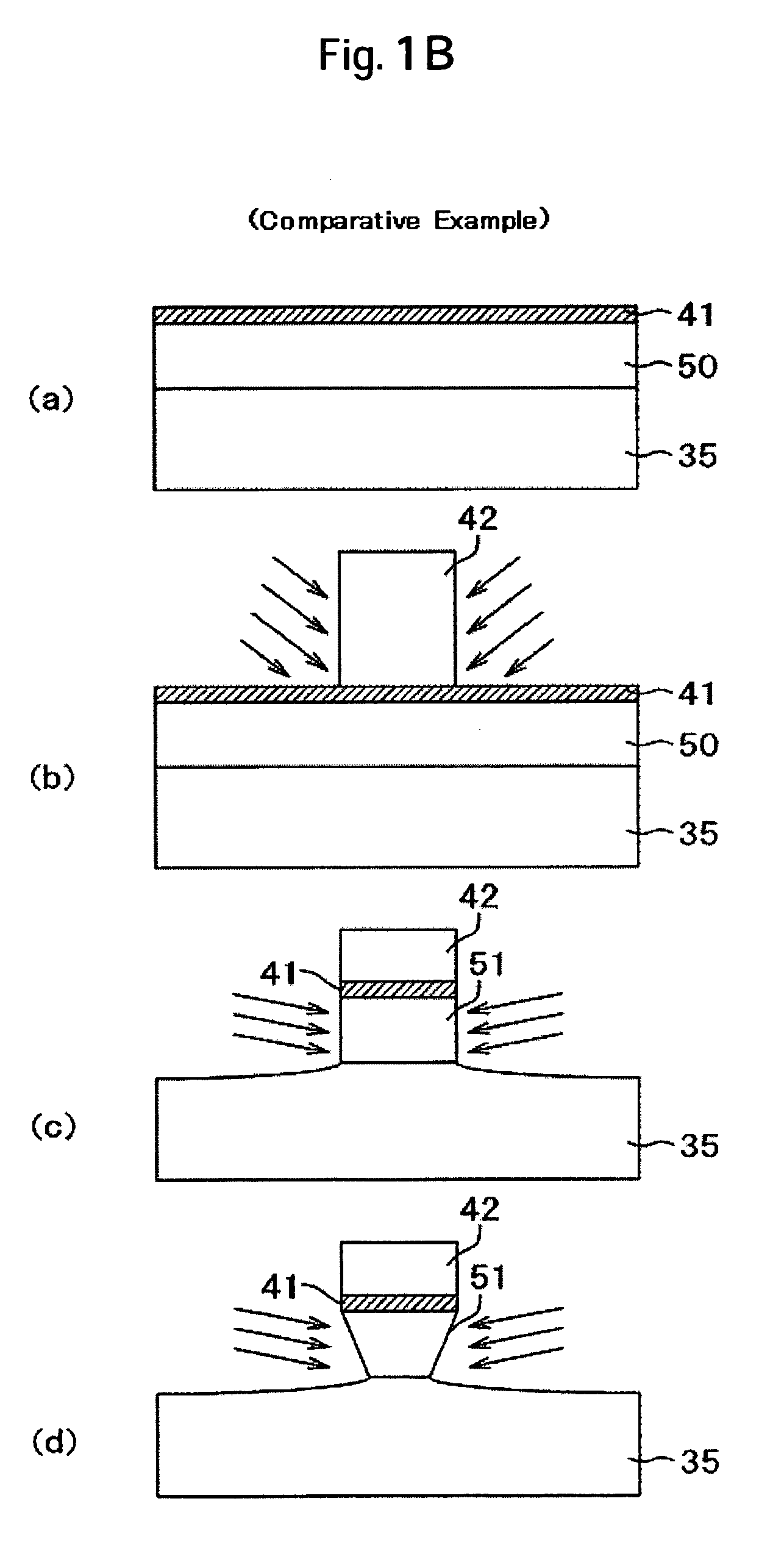
In this case, while an ion milling method is used for attaining the inverted trapezoidal shape, long milling time poses a problem of variations of the inverted trapezoidal shape and variations of the track width due to dimensional shift.
While the method described in Patent Document 1 prepares the inverted trapezoidal shape by a plating method, no sufficient consideration is made on the dimensional variations of the track width, etc. upon preparation of the inverted trapezoidal shape for the narrow track width.
However, since a non-magnetic metal film such as alumina is present as a gap material below the main magnetic pole, the method involves a drawback in which the portion below the main magnetic pole is hard to scrape, making it difficult to form the inverted trapezoidal shape.

Method used


Image

  • Method of manufacturing a magnetic head
  • Method of manufacturing a magnetic head
  • Method of manufacturing a magnetic head

Examples


Embodiment Construction

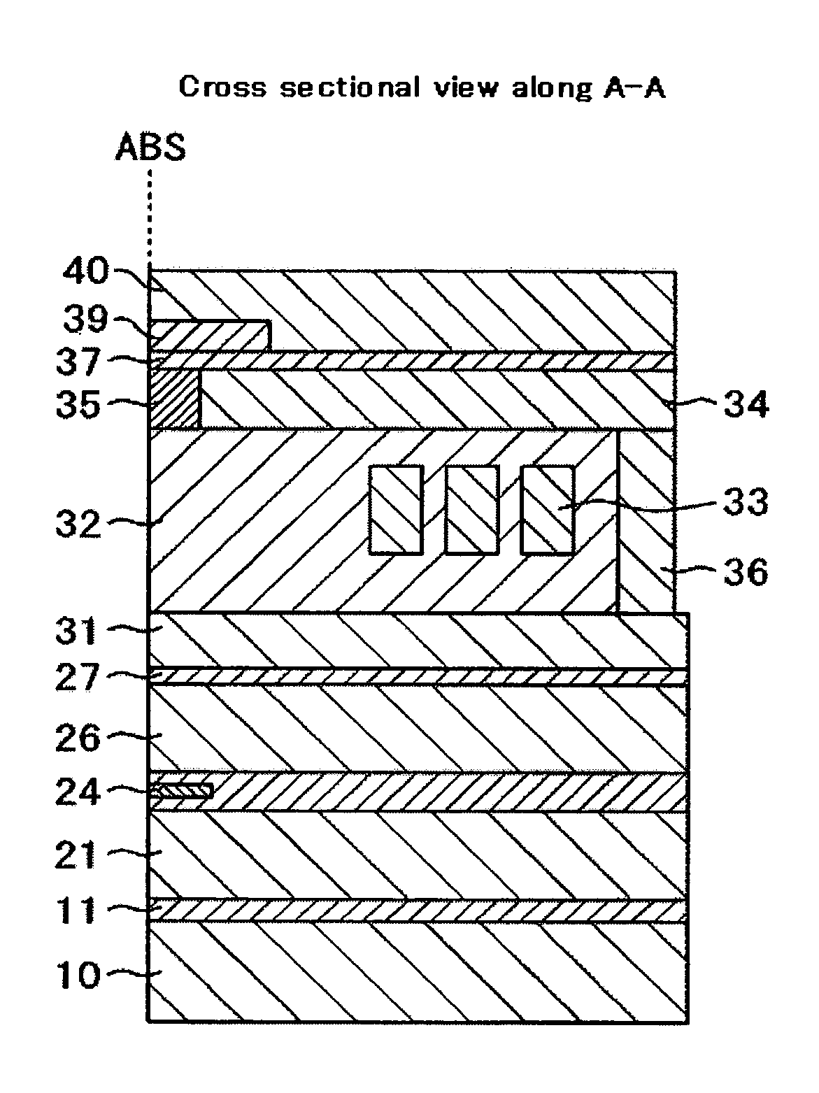
[0029]Embodiments of the present invention will be described in detail with reference to the drawings. In the drawings, like constituent portions or functional portions carry the same reference numerals for easy understanding. FIG. 7 is a schematic constitutional view of a magnetic disk drive on which a magnetic head for perpendicular recording (hereinafter simply referred to as a magnetic head) according to an embodiment is mounted. FIG. 7A shows a plan view with a cover detached and FIG. 7B is a cross sectional view of a spindle motor and an actuator. The magnetic disk drive records and reproduces magnetization signals by a magnetic head 1 fixed to the top end of a suspension 2 on a magnetic disk 5 rotationally driven by a spindle motor 6. The suspension 2 is attached to an arm 3, and the arm 3 is supported by the actuator 4. The magnetic head is driven in the radial direction of the disk by the actuator 4 and positioned over a track 7 for read and write. Write signals supplied to...


PUM

PropertyMeasurementUnit
angleaaaaaaaaaa
heightaaaaaaaaaa
thicknessaaaaaaaaaa

Abstract

A main magnetic pole of a recording head is formed in an inverted trapezoidal shape by ion milling but, the long milling time poses a problem of variations in the inverted trapezoidal shape and the dimensional variations in track width. In one embodiment of the invention, a recording head is formed by first forming a lower magnetic pole, a gap layer, and conductor coils, forming an upper magnetic yoke over the gap layer at a position recessed from the air bearing surface, and forming an inorganic insulative layer in the recessed portion. A back magnetic pole connected with the upper magnetic yoke is formed on the back of the lower electrode. Successively, the upper surfaces of the inorganic insulative layer and the upper magnetic yoke are planarized, on which an underlayer film such as of Rh is formed. A magnetic layer is formed by stacking a plurality of thin magnetic films by sputtering over the underlayer film from the air bearing surface as far as the position overlapping the upper magnetic yoke. Successively, ion milling is applied to form a main magnetic pole of an inverted trapezoidal shape having a taper on the lateral surface as viewed from the air bearing surface.

Description

CROSS-REFERENCES TO RELATED APPLICATIONS[0001]This application claims priority from Japanese Patent Application No. JP2005-123433, filed Apr. 21, 2005, the entire disclosure of which is incorporated herein by reference.BACKGROUND OF THE INVENTION[0002]The present invention relates to magnetic heads used for reading and writing data from and to a magnetic recording medium and manufacturing methods thereof and, more in particular, it relates to a magnetic head suitable for perpendicular magnetic recording and a manufacturing method thereof.[0003]In magnetic disk apparatus, data on a recording medium is read and written by a magnetic head. To increase the recording capacity per unit area of the magnetic disk, it is necessary to increase the areal density. However, a current longitudinal recording system involves a problem in that the areal density cannot be increased because of thermal fluctuation over the magnetization of the medium as recordable bit length is smaller.[0004]Methods ca...

Claims


Application Information

Patent Timeline
Patent Type & Authority Patents(United States)
IPC IPC(8): G11B5/187
CPCG11B5/1278G11B5/3116G11B5/3163Y10T29/49046Y10T29/4906Y10T29/49041Y10T29/49043
Inventor KATO, ATSUSHIOOKAWA, NORIHIROKIMURA, HISASHI
Owner WESTERN DIGITAL TECH INC
Learn More