Cooling system, and internal combustion engine comprising a cooling system of said type

a cooling system and internal combustion engine technology, applied in the direction of liquid cooling, engine components, machines/engines, etc., can solve the problems of reducing the efficiency of cooling and the heat capacity of the mixture of coolant and air present in the line section under consideration, and avoiding the risk of apertures being interchanged, so as to avoid the risk of particle blockage in the coolant. , the effect of avoiding the risk of oscillation

Active Publication Date: 2017-07-20
ROLLS ROYCE SOLUTIONS GMBH
View PDF6 Cites 2 Cited by
  • Summary
  • Abstract
  • Description
  • Claims
  • Application Information

AI Technical Summary

Benefits of technology

[0007]The present invention provides a cooling system which has at least one first component to be cooled, into which a first coolant line opens, wherein a first ventilation line which is different from the first coolant line is fluidically connected to the first component for the purposes of ventilation of the first component. Here, it is provided that the first ventilation line opens into a second coolant line. The ventilation line extending from the first component is thus led not to a central infeed point such as an expansion tank or a bubble separator but rather—in decentralized fashion—into a second coolant line, such that the air discharged from the first component can be conveyed onward through the second coolant line along the coolant circuit. By this decentralized configuration, it is possible for the ventilation line, for example even in the case of the first component to be cooled being arranged remote from an expansion tank, to be of shorter form than if a central introduction point and a merging of multiple ventilation lines were provided. In this way, disadvantages associated with long ventilation lines—in particular of a design nature and with regard to mounting and susceptibility to oscillations—can be at least substantially—or even entirely—avoided. Furthermore, there is no longer a risk of apertures being interchanged. Rather, it is possible for identical aperture diameters to be used for different ventilation lines, such that identical parts can be used. Since there is no longer a need for equalization of different pressure levels of a multiplicity of components at a central introduction point, it is also possible for aperture diameters to be selected to be larger, such that a risk of blockage by particles present in the coolant is avoided.

Problems solved by technology

There is however the problem that the heat capacity of a mixture of coolant and air present in a line section under consideration is reduced in relation to pure coolant, and thus the efficiency of the cooling is reduced.
Furthermore, air cushions can form at geodetically high points of components to be cooled, which air cushions may possibly considerably reduce a coolant throughflow or even bring such a throughflow to a complete standstill.

Method used


Image

  • Cooling system, and internal combustion engine comprising a cooling system of said type
  • Cooling system, and internal combustion engine comprising a cooling system of said type
  • Cooling system, and internal combustion engine comprising a cooling system of said type

Examples


Embodiment Construction

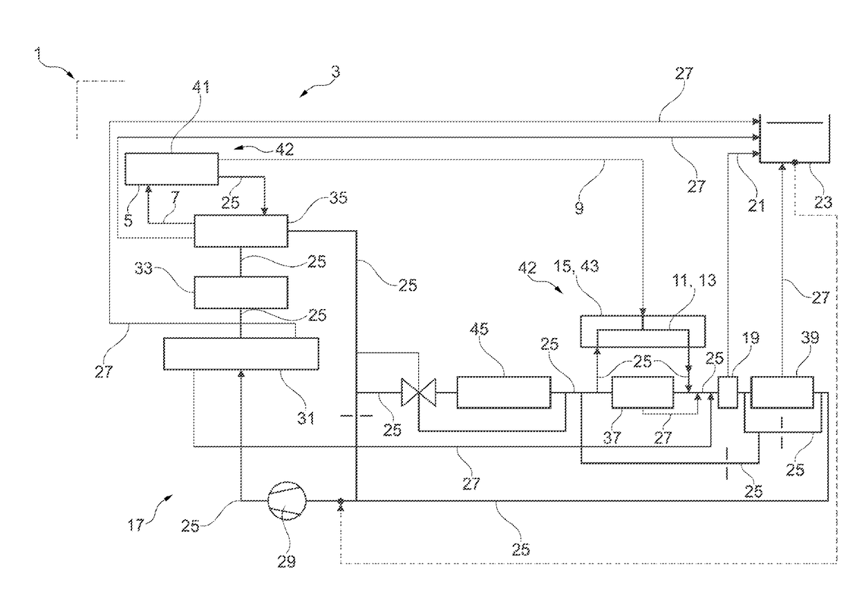
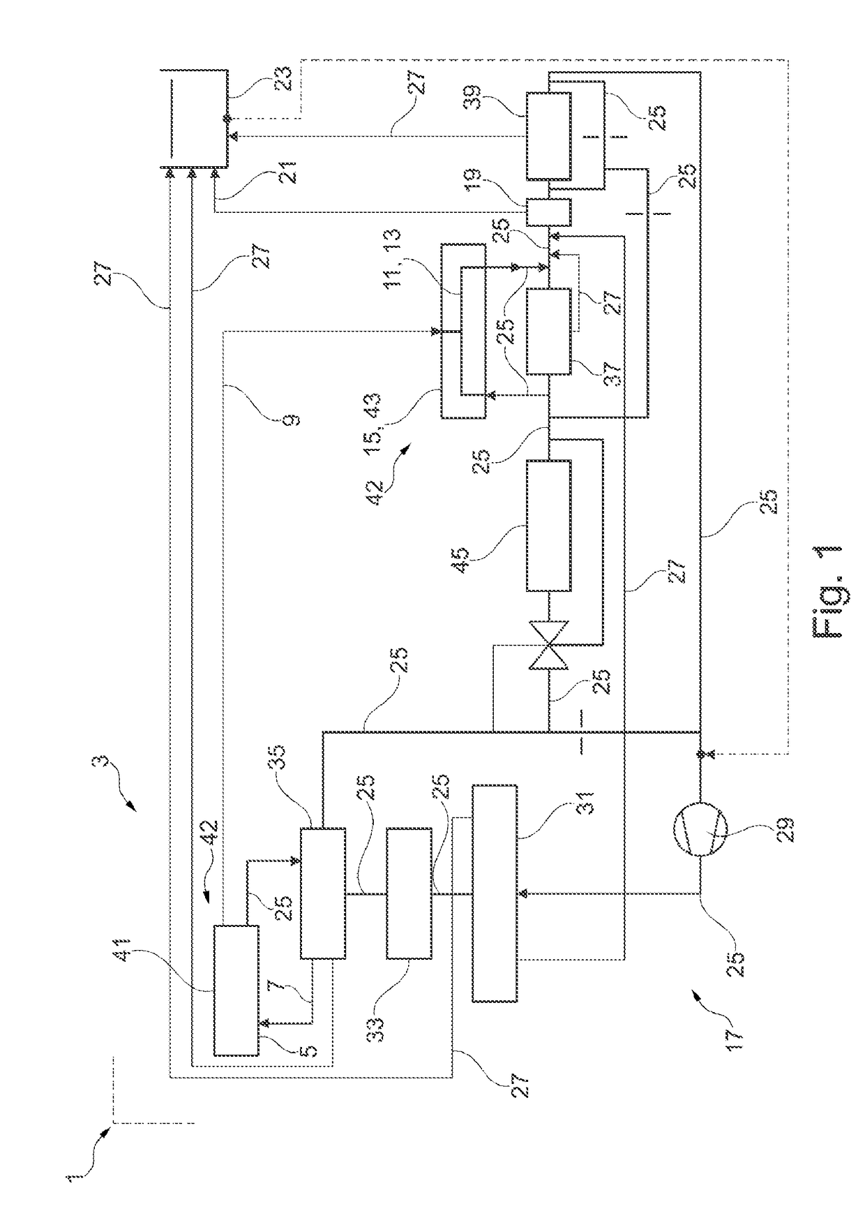
[0064]FIG. 1 is a schematic illustration of a first exemplary embodiment of an internal combustion engine 1 with a cooling system 3. The cooling system 3 has a first component 5 to be cooled, into which a first coolant line 7 opens. A first ventilation line 9, which is different from the first coolant line 7, is fluidically, i.e. fluidly, connected to the first component 5 for the purposes of ventilating the latter. The first ventilation line 9 opens into a second coolant line 11.

[0065]Here, the second coolant line 11 is formed as a coolant path 13 which is formed in a second component 15 to be cooled, for example in the form of a double-walled housing of the second component 15.

[0066]Alternatively, it is also possible for the first ventilation line 9 to open, outside a component to be cooled, into a coolant line of a coolant circuit 17 of the cooling system 3. This even constitutes a variant, because then no further component is impinged on by the air ventilated from another compon...


PUM


Abstract

A cooling system including a first coolant line and a second coolant line, at least one first component to be cooled, into which the first coolant line opens, and a first ventilation line. The first ventilation line is fluidically connected to the at least one first component and is configured for ventilating the at least one first component. The first ventilation line opens into the second coolant line.

Description

CROSS REFERENCE TO RELATED APPLICATIONS[0001]This is a continuation of PCT application No. PCT / EP2015 / 072748, entitled “COOLING SYSTEM, AND INTERNAL COMBUSTION ENGINE COMPRISING A COOLING SYSTEM OF SAID TYPE”, filed Oct. 1, 2015, which is incorporated herein by reference.BACKGROUND OF THE INVENTION[0002]1. Field of the Invention[0003]The present invention relates to cooling systems, and, more particularly, to an internal combustion engine having a cooling system.[0004]2. Description of the Related Art[0005]A cooling system generally has a coolant circuit through which a liquid coolant flows for the purposes of absorbing heat from components to be cooled, for example of an internal combustion engine. During filling or refilling with coolant, or as a result of leaks that may exist in a cooling system, air pockets may form, which have an adverse effect on a level of cooling power of the cooling system. For this purpose, in the case of known cooling systems, it is provided that a ventil...

Claims


Application Information

Patent Timeline
Patent Type & Authority Applications(United States)
IPC IPC(8): F01P11/02F01P3/20F01P11/04
CPCF01P11/0285F01P11/04F01P2060/12F01P3/20F01P11/029F02B39/005
Inventor MARKIN, OLIVER
Owner ROLLS ROYCE SOLUTIONS GMBH
Why Eureka
Try Eureka