However, since the conventional LCDs are low in response speed, they have a drawback that it is difficult to reproduce motion pictures.
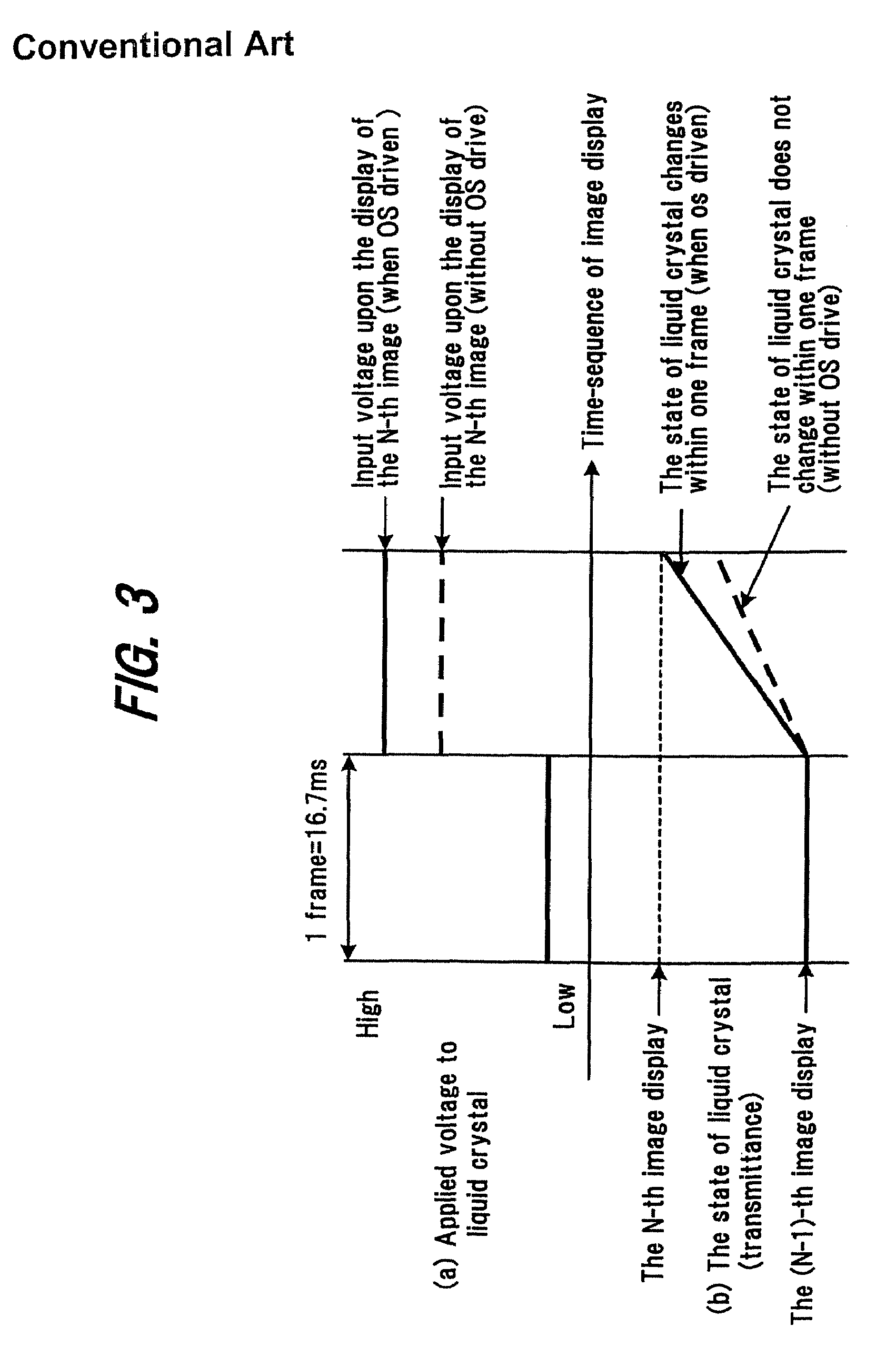
There has been a problem in that it takes long time to make a transition from a certain half gray scale level to another half gray scale level, so that it is impossible for a general liquid crystal display panel to display the half gray scales within the period of one frame (e.g., 16.7 msec. for a case of progressive scan of 60 Hz).
This not only produces afterglow but also hinders correct half gray scale display.
However, if the emphasis-converted data is mis-optimized, errors in data between frames are enhanced, so that video noise which does not originate from due input data will be generated. FIGS. 4 and 5 show the relationships between the applied voltage to the liquid crystal display panel and the transmittance when the input video data changes from black to a certain half gray scale value.
However, if the input data changes repeatedly, e.g., black→half gray scale→black→half gray scale, the error will rapidly increase.
In terms of normally received television signals this problem causes undue images (so-called noise) that are laid over edges such as face contours, character contours, etc., resulting in image degradation such as unnatural hue, white spots, flickering, etc.
Further, when the response speed of the liquid crystal display panel is taken into consideration, it is difficult to output the optimal emphasis-converted data at any time because of variations in cell gap, change in the viscosity of the liquid crystal material due to ambient temperature and other factors.
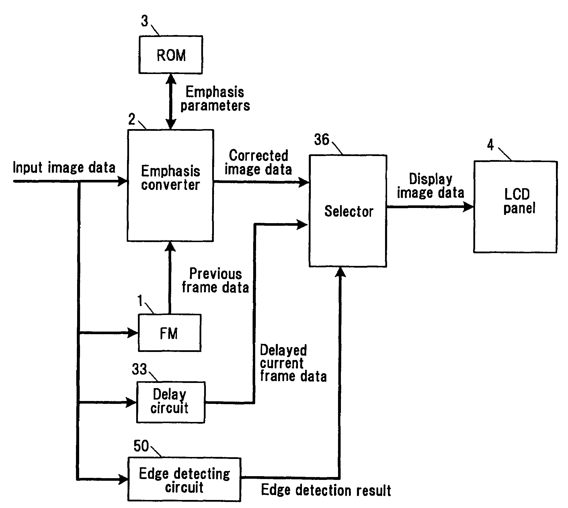
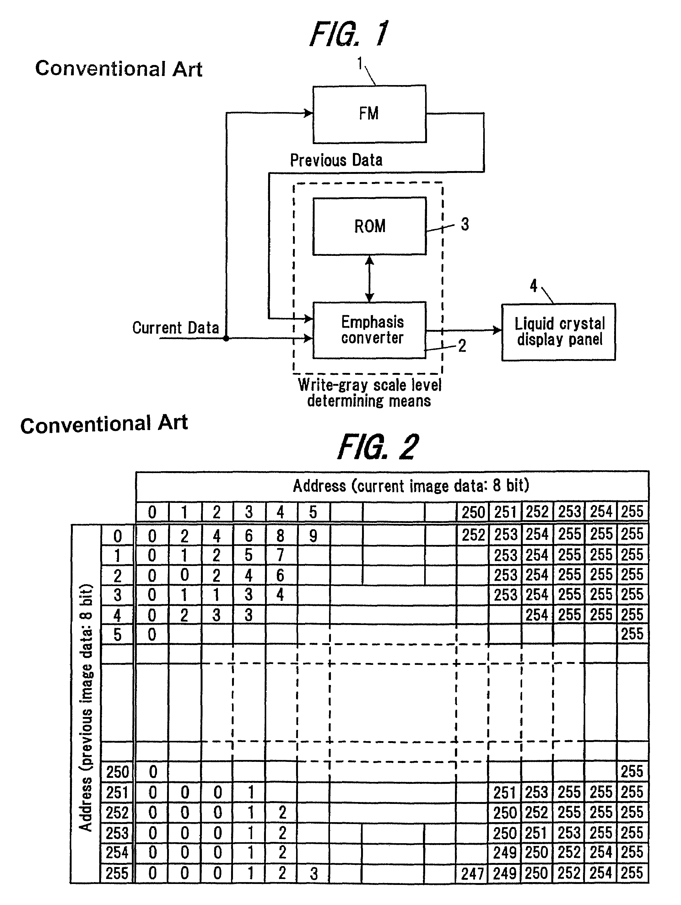
Further, since in the conventional liquid crystal display shown in FIG. 1, the input image data for the current frame is emphasis-converted and supplied to the liquid crystal display panel, based on the gray scale level transitions of the input image data from one frame to the next, if some noise is laid over the input image data, the noise also is emphasis-converted and supplied to the liquid crystal display panel, causing image degradation such as white spots, flickering etc., resulting from the emphasized noise.
On the other hand, when OS drive for data emphasis conversion is implemented, this affects the data to enlarge the transition width.
In this way, if a signal source of a poor S / N ratio is supplied to an OS drive configuration, the noise is also emphasized more than that in the normal drive mode, this gives a problem in that the image quality of the displayed image is degraded.
Therefore it has been impossible to prevent image degradation of the displayed image, in a perfect manner.
In the conventional liquid crystal display shown in FIG. 1, when the emphasizing process (OS drive) by write-gray scale level determining portion 2 is implemented, noise and the like, which are high frequency components, superimposed on the input image data, are further emphasized by the OS drive, posing the image degradation problem in that noise stands out as white spots (in the case of the liquid crystal display panel operated in the normally black mode).
For example, playback of an analog VTR entails noise that is attributed to the tape and head system during signal reproduction, or playback of a tape that is obtained after repeated duplication results in a poor signal to noise ratio producing much noise.
If the above-described OS drive is implemented for the input image data superimposed with such noise, even the noise is emphasized and results in image degradation of the displayed image.
Further, when a user who prefers a clear and vivid image adjusts the contour enhancement correcting function of a television system etc., to a severe level, the contour enhanced portions are further emphasized by OS drive to a too strong level and unnatural hues, flickering, etc., arise, degrading the image quality of the displayed image.
This noise is generated due to loss of high frequency components that are included in the original image signal, through quantization.
In this way, when coded image data that is encoded based on a coding scheme that implements blockwise orthogonal transformation is input / decoded to perform image display, block distortion whereby boundaries of process blocks appear in the flat portion of the decoded image, and mosquito noise that causes haze around edge portions of characters and contours occur.
Accordingly, depending on the video adjustment result, OS drive may pose a problem in that the image quality of the displayed image is degraded by the occurrence of the adverse effects (unnatural hues, flickering, etc.) therefrom.
For example, when a user who prefers a clear and vivid picture applies rather intensive contour enhancement correction by video adjustment, the contour enhanced portions are further emphasized by OS drive to a too strong level and produce white spots (in the case of a liquid crystal display panel operated in the normally black mode), unnatural hues, flickering and others, resulting in degradation of the image quality of the displayed image.
When a picture obtained as a result of the user's video adjustments for input image data as to gray scale level characteristics such as black (white) extension, black (white) level adjustment, brightness adjustment and the like, includes many gray scale level transition patterns of which the liquid crystal response speed cannot be improved very much by OS drive (emphasis conversion process), implementation of OS drive only enlarges data errors between frames, resulting in generation of video noise which does not exist in the original input image data.
As a result, gray scale levels which are deviated from due gray scale levels to be displayed are displayed, so that the desired image cannot be displayed.
If this is repeated, the error of the output data increase rapidly, posing the problem in that whitened or blackened pixels are reproduced.
The above-described conventional liquid crystal display, however, has the following problems.(1) If, for example, the applied voltage data (emphasis conversion parameters) stored in OS table memory 3 is broken, or the calculation algorithm for linear interpolation or the like in emphasis converter 2 is broken, due to some device trouble, it becomes impossible to supply the liquid crystal display panel 4 with correct applied voltages of data (emphasis-converted data) corresponding to the input image data, whereby the image quality of the displayed image is markedly degraded, thus hindering the attention to the picture.(2) Further, in the case of the above-described conventional liquid crystal display, in the normal installed state (stand-mounted state) shown in FIG. 9(a) temperature sensor 16 is arranged at the place where it has least influence of heat from inverter transformer 12, power supply unit 13 and other components.
However, when the screen is set at the vertically inverted state (in the suspended state from ceiling) as shown in FIG. 9(b) or when rotated by 90 degrees (in the portrait orientation state) as shown in FIG. 9(c), the heat flow path changes hence temperature sensor 16 is significantly affected by generation of heat from the other members, so it is no longer possible to detect the exact temperature of liquid crystal display panel 4.
As a result, correct applied voltages of data (emphasis-converted data) corresponding to the temperature of liquid crystal display panel 4 cannot be supplied to liquid crystal display panel 4, causing the problem of image quality of the displayed image being significantly degraded by generation of shadow tailing due to application of insufficient applied voltages of data (emphasis-converted data) to liquid crystal display panel 4 or by generation of white spots due to application of excessive applied voltages of data (emphasis-converted data) to liquid crystal display panel 4 (in the case of the normally black mode).
This problem of varying temperature distribution across the surface of liquid crystal display panel 4 depending on the place of installation becomes more noticeable when the display screen size becomes greater.(3) Moreover, when coded image data that is encoded based on a coding scheme that implements orthogonal transformation for every block consisting of, for example, M×N pixels, is input / decoded to perform image display, block distortion whereby boundaries of processed blocks appear in the flat portion of the decoded image, and mosquito noise that causes haze around edge portions of characters and contours occur, depending on the compression ratio of the image coded data.
When overshoot drive is applied to these noises, the noises are emphasized, resulting in degradation of the image quality of the displayed image.
Similarly and also, in the case where a picture signal having a poor S / N ratio is input, the noise is emphasized when overshoot drive is effected, causing degradation of the image quality of the displayed image.
In this way, depending on the property of the input image, overshoot drive causes adverse effect, thus degrading the image quality of the displayed image.

