
Interferometer and shape measuring method

a technology of interferometer and shape, applied in the direction of interferometer, measurement device, instruments, etc., can solve the problems of difficult to measure a target surface with large waviness, strict efforts, interference noise, etc., and achieve the effect of avoiding interference noise and easily adjusting the arrangement of a measuring obj

Active Publication Date: 2008-07-08
MITUTOYO CORP
View PDF8 Cites 15 Cited by
  • Summary
  • Abstract
  • Description
  • Claims
  • Application Information

AI Technical Summary

Benefits of technology

[0007]The present invention has been made in consideration of the above subject and has an object to provide an interferometer capable of avoiding interference noises and easily adjusting the arrangement of a measuring object. A shape measuring method using the interferometer is also provided.
[0010]The present invention provides an interferometer capable of avoiding interference noises and easily adjusting the arrangement of a measuring object. A shape measuring method using the interferometer is also provided.

Problems solved by technology

On measurement of a parallel glass substrate, however, a light reflected from a front surface to be measured (a target surface) and a light reflected from an undesired, rear surface may interfere with each other, resulting in interference noises.
Therefore, this makes it difficult to measure a target surface with large waviness and requires strict efforts by a skilled worker on setting of a measuring object.

Method used


Image

  • Interferometer and shape measuring method
  • Interferometer and shape measuring method
  • Interferometer and shape measuring method

Examples


first embodiment

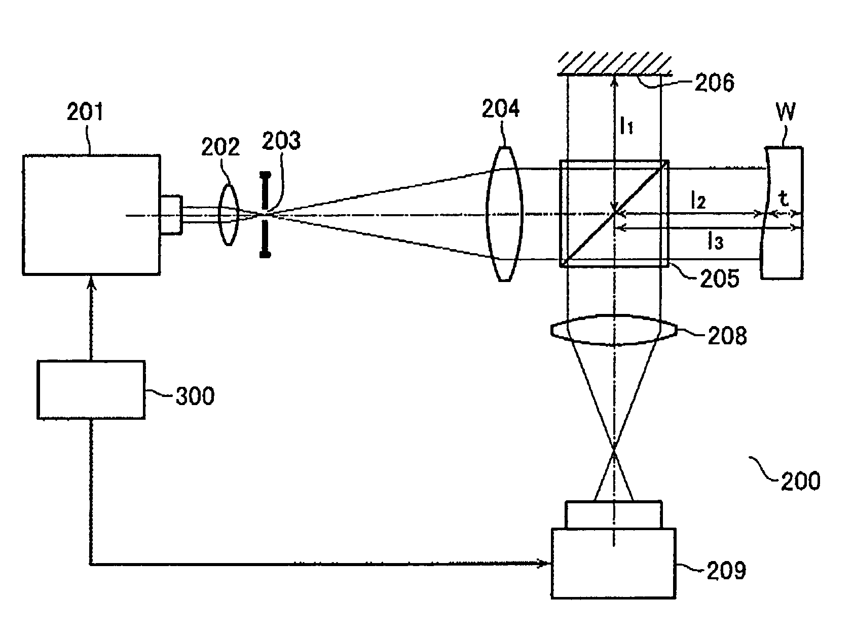
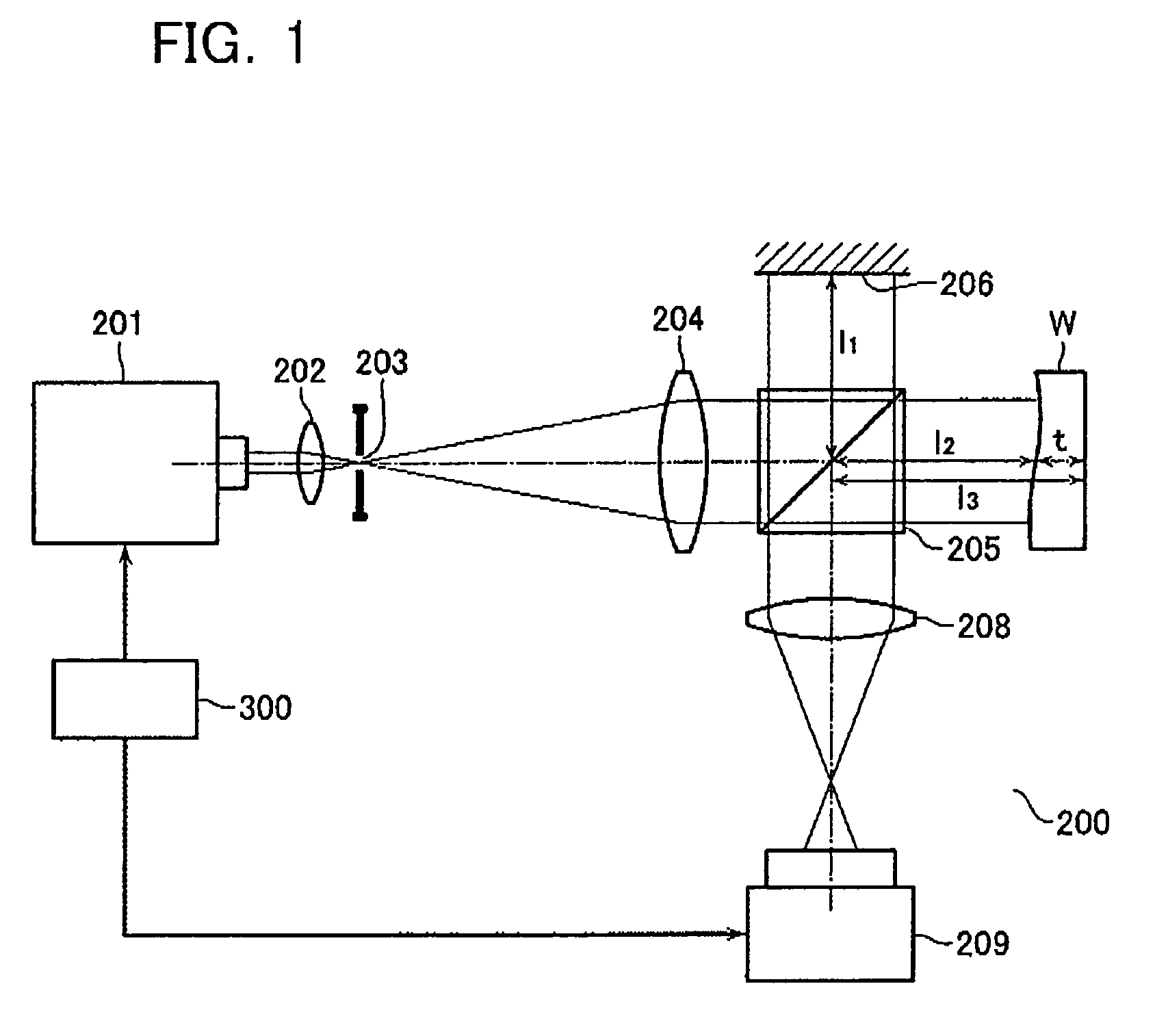
[0023]FIG. 1 is a schematic diagram of a configuration of an interferometer according to a first embodiment of the present invention. The interferometer 200 shown in FIG. 1 comprises a wavelength-variable light source 201, a condenser lens 202, a pinhole 203, a collimator lens 204, a beam splitter 205, a reference mirror 206, a lens 208, and a CCD camera 209. A measuring object W herein is a transmissive object with a thickness of t, having a front surface that is a target surface and a rear surface that reflects a light.

[0024]The wavelength-variable light source 201 is a laser light source adjusted to emit a laser light in a single longitudinal mode, of which center wavelength λ0 is controlled by a control signal from a controller 300 to vary over a wavelength scan width, then wavelength λ of the wavelength-variable light source 201 is varied within λ=λ0±Δλ / 2, where Δλ denotes a wavelength scan width (for wavelength scanning within ±Δλ / 2 about the wavelength λ0). The controller 300...

second embodiment

[0060]An interferometer according to a second embodiment of the present invention is described next with reference to FIG. 6. Elements in FIG. 6 in common with those in the first embodiment are given the same or corresponding reference numerals and omitted from the following detailed description. The interferometer of this embodiment is such an interferometer that acquires interference fringes having optically different phase differences at the same time to execute a phase shifting method, different from the first embodiment.

[0061]The light emitted from the wavelength-variable light source 201 is split through a polarizing beam splitter 205′ into orthogonal, linearly polarized lights: a measurement light and a reference light. The measurement light and the reference light are converted from linearly polarized lights into circularly polarized lights through a ¼-wavelength plate 210 and a ¼-wavelength plate 211, and then reflected from the measuring object W and the reference surface ...

third embodiment

[0065]An interferometer according to a third embodiment of the present invention is described next with reference to FIG. 8. The interferometer according to this embodiment is also an interferometer that uses a phase shifting method, like the second embodiment. Different from the second embodiment, the ¼-wavelength plate 212 between the polarizing beam splitter 205′ and the beam splitter 213A is omitted while a ¼-wavelength plate 215 is newly arranged in front of the polarizing plate 214B. The ¼-wavelength plate 215 has a fast axis orientation and a slow axis orientation, which are made coincident with the polarizing directions of the reference light and the measurement light, thereby providing a relative phase difference of 90° between the reference light and the measurement light.

[0066]The polarizing plates 214A, 214B, 214C have respective transmission axes set at angles of α, α, α+90° as shown in FIG. 9. The angle α may have any orientation unless it is quite identical to the ori...


PUM


Abstract

A wavelength-variable light source is configured to emit a light with a wavelength (λ), which is variable within a scan width (Δλ). An interferometer has a coherent length (ΔL), which is determinable from (Δλ) and (λ). A controller determines an appropriate magnitude of the scan width (Δλ) while a CCD camera captures a fringe image in an exposure time (Te), which is set longer than a time for wavelength scanning.

Description

CROSS REFERENCE TO RELATED APPLICATION[0001]This application is based upon and claims the benefit of priority from the prior Japanese Patent Application No. 2005-145035, filed on May 18, 2005, and No. 2006-029167, filed on Feb. 7, 2006, the entire contents of which are incorporated herein by reference.BACKGROUND OF THE INVENTION[0002]1. Field of the Invention[0003]The present invention relates to an interferometer for use in measurement of the shape of a measuring object based on interference fringes, and a shape measuring method using the interferometer.[0004]2. Description of the Related Art[0005]An interferometer for use in measurement of flatness generally incorporates a high-coherence light source such as a He—Ne laser. On measurement of a parallel glass substrate, however, a light reflected from a front surface to be measured (a target surface) and a light reflected from an undesired, rear surface may interfere with each other, resulting in interference noises. The use of a lo...

Claims


Application Information

Patent Timeline
Patent Type & Authority Patents(United States)
IPC IPC(8): G01B11/02
CPCG01B9/02004G01B9/02048G01B9/02081G01B2290/45G01B2290/70
Inventor KAWASAKI, KAZUHIKOSUZUKI, YOSHIMASASESKO, DAVID W.
Owner MITUTOYO CORP
Learn More