Foldaway bed frames and spring supports

Inactive Publication Date: 2008-07-15
MERRITT BERNARD
View PDF16 Cites 13 Cited by
  • Summary
  • Abstract
  • Description
  • Claims
  • Application Information

AI Technical Summary

Benefits of technology

[0012]It is an aspect of the present invention to provide legs that operate independently of any mechanical rods or connections. Utilizing a pivot connection and gravity to correctly position the legs when the bed is lowered avoids the complexity of the prior design as well as its susceptibility to damage during use. This manner of operation also permits the positioning of the legs further underneath the bed, lessening the opportunity for users to inadvertently strike the legs after the bed is lowered.
[0013]Another aspect of the present invention provides a collapsible bed frame that may be assembled on-site and in varied widths to accommodate multiple bed sizes. The manufacturer can rely upon “retail” shipping methods, while the foldaway bed sellers need set aside significantly less storage space. Sellers can obtain more reliable and less expensive shipments of bed frames, as required by customer demand. In addition, only a small inventory provides the seller the ability to offer multiple bed frame sizes to meet the sometime unpredictable demand of its customers.
[0014]Another aspect of the present invention enhances the mechanical advantage of the foldaway bed tension springs by alternative base frame designs. In a first design the rotational pivot is moved inward from the face of the frame. Such pivot relocation provides a greater mechanical advantage to the tension spring connection with the bed frame, enabling the use of fewer springs to accomplish the needed counterweight action.
[0015]A second design utilizes a two-tiered bracket and spring arrangement. Springs can easily be added to balance the load factor if heavier beds or front panels are used. Additionally, the superior mechanical advantage provided by the double bracket design enables the use of much heavier front panels when designing foldaway bed sets.

Problems solved by technology

In addition, only a small inventory provides the seller the ability to offer multiple bed frame sizes to meet the sometime unpredictable demand of its customers.

Method used


Image

  • Foldaway bed frames and spring supports
  • Foldaway bed frames and spring supports
  • Foldaway bed frames and spring supports

Examples


Embodiment Construction

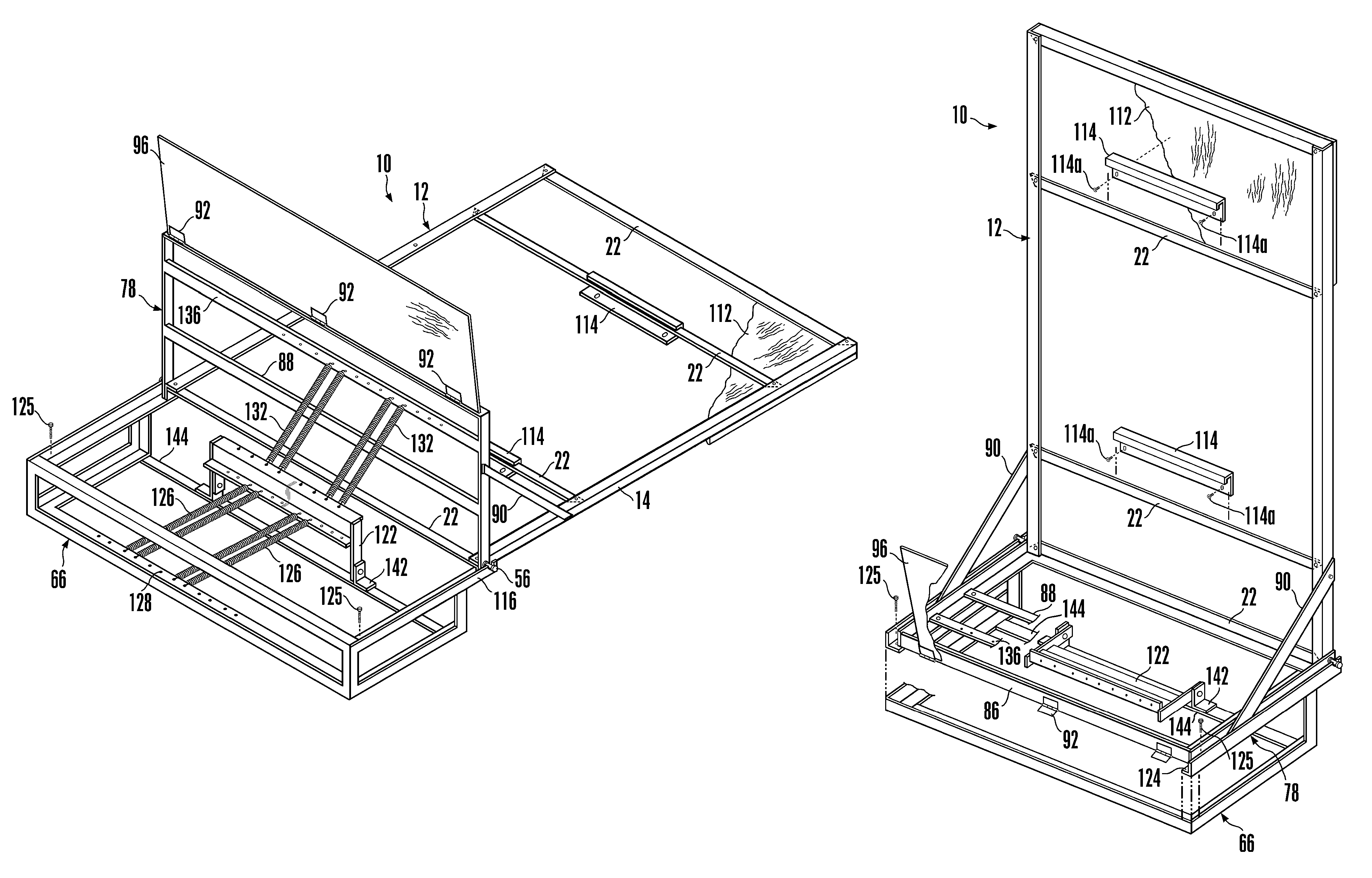
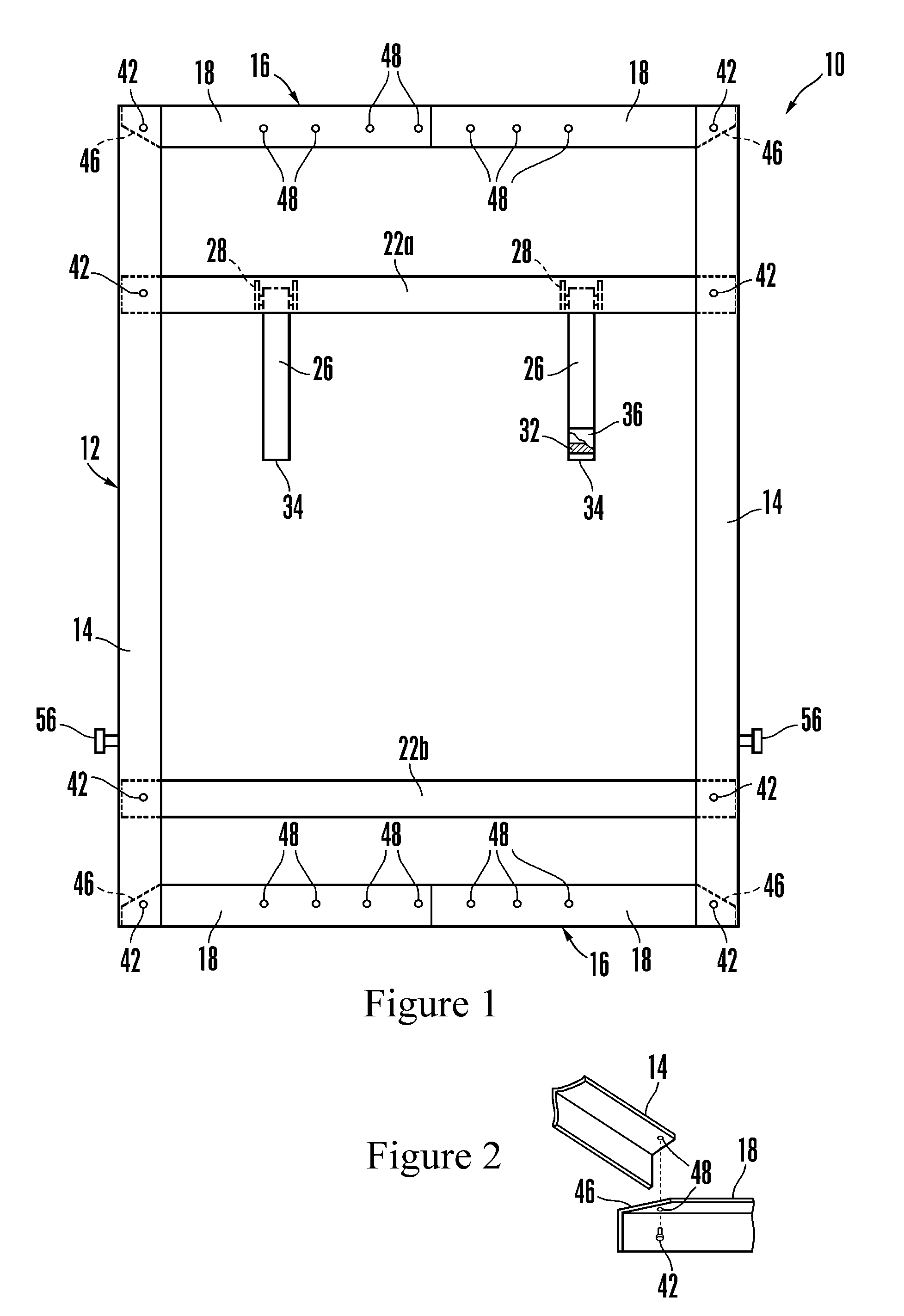
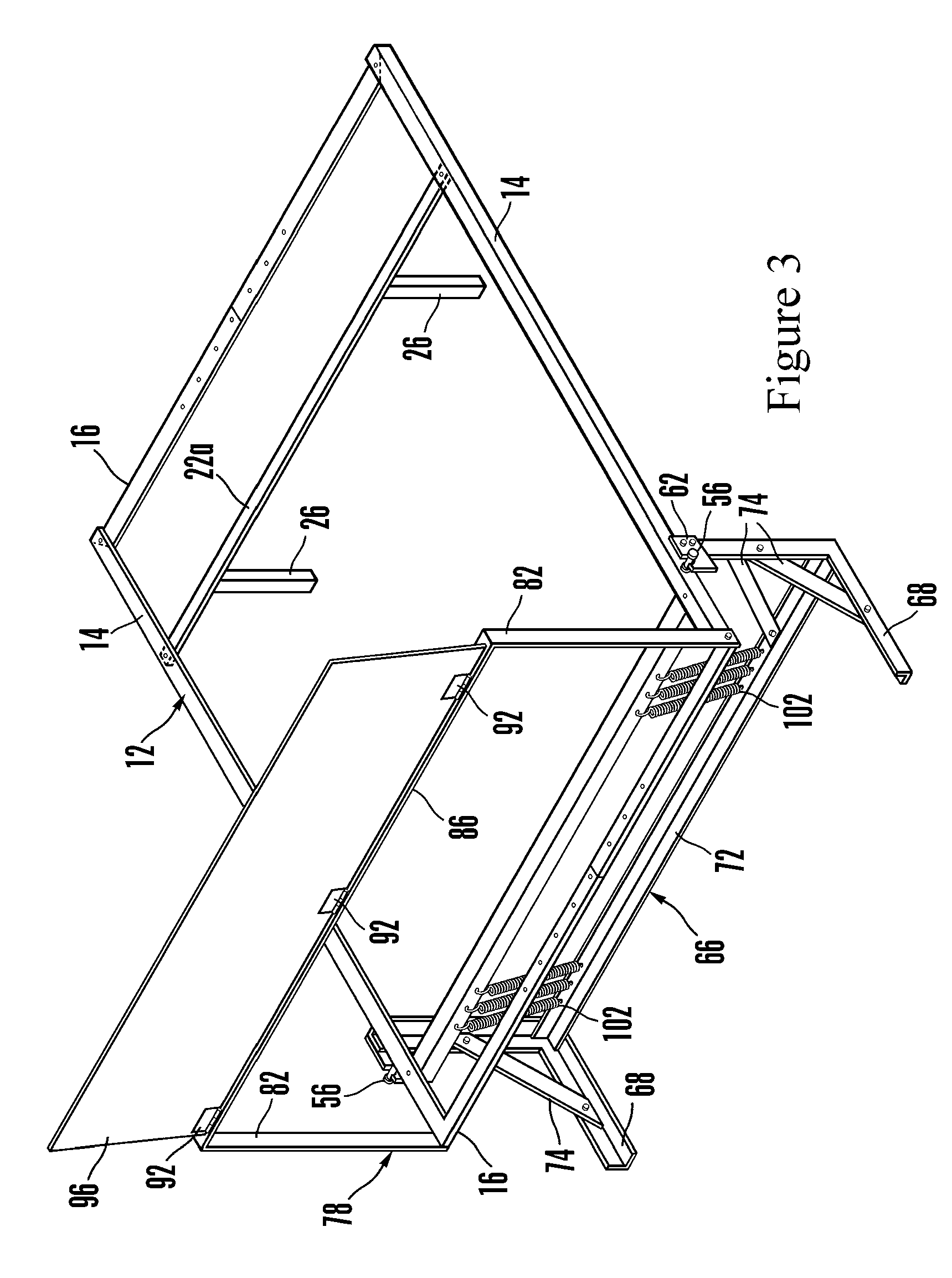
[0026]Reference is now made to the drawings wherein like numerals refer to like parts throughout. In FIG. 1, a bed frame 10 is constructed in a collapsible manner to greatly simplify its manner of shipment to wholesalers as well as minimize inventory concerns. Typically fabricated from angle irons of cold rolled steel, the bed frame 10 includes a mattress support frame 12 that consists of a pair of longitudinal support rails 14 attached to one another by a pair of cross-support rails 16. Each of the cross-support rails consist of a pair of support arms 18 that respectively extend from an attachment location on the longitudinal support rails 14 to a central attachment location that connects the pair of support arms 18.

[0027]Additional strengthening of the mattress support frame 12 is provided by solid cross-frame members 22. In addition to providing greater rigidity to the mattress support frame 12, the cross-frame members 22 can additionally provide support for other bed frame attac...


PUM


Abstract

A folding bed frame utilizes a spring support bracket that is located intermediate a bed support frame and a mattress support frame. Separate pairs of tensioning springs attach the spring support bracket to the bed support frame and to the mattress support frame. This tiered spring arrangement provides an enhanced counterweighting force to the mattress support frame, assisting a user when raising or lowering the bed. Additionally, a hanger is attached to a rear surface of a front panel to assist in the proper positioning of the panel prior to its attachment to the mattress support frame.

Description

CROSS-REFERENCE TO RELATED APPLICATION[0001]This application claims the benefit of U.S. Provisional Application Ser. No. 60 / 596,572, filed Oct. 4, 2005.FIELD OF THE INVENTION[0002]The present invention relates to beds and, more particularly, to beds that fold into a wall or storage cabinet. More specifically, the present invention relates to a folding front panel bed having improvements in its spring support and manner of panel attachment.DESCRIPTION OF THE PRIOR ART[0003]Known as an idea whose time has come, gone, and come again, the Murphy bed (also known as wall-beds, door and foldaway beds) was invented in California by William K. Murphy around the turn of the last century. By 1927 the Murphy In the Door Bed Co. was a $30 million a year business with factories in San Francisco, Chicago, and New York. Amazingly, the company lasted until the early 1980's; however, by the end of that decade, a court decided that the “Murphy” trademark could be used by any company to describe a fold...

Claims


Application Information

Patent Timeline
IPC IPC(8): A47C19/12
CPCA47C19/12A47C17/40
Inventor MERRITT, BERNARD
Owner MERRITT BERNARD
Why Eureka
Try Eureka