Method and system for detecting objects in a vehicle blind spot

Active Publication Date: 2020-07-02
FICOSA ADAS S L U
View PDF0 Cites 1 Cited by
  • Summary
  • Abstract
  • Description
  • Claims
  • Application Information

AI Technical Summary

Benefits of technology

This patent aims to provide a system for vehicles that can avoid collisions and reduce complexity by using a single camera per vehicle side and developing scenarios for lane changes. The system can help the driver avoid collisions with high-speed vehicles in the rear zone and adjacent zones when making lane changes. Overall, this invention offers improved safety and efficiency for driving.

Problems solved by technology

When the driver wants to change lanes, the driver cannot see any vehicle in this blind spot, so that side collisions are possible.
These systems are intended to supplement the vehicle's exterior rear-view mirrors, not eliminate the need for such mirrors.
Existing blind spot detection systems have difficulty differentiating between a stagnating vehicle and a stationary object.
Failure to distinguish between a stagnating vehicle and a stationary object limits the effectiveness of the blind spot detection system and leads a driver to mistrust warnings produced by the system.

Method used


Image

  • Method and system for detecting objects in a vehicle blind spot
  • Method and system for detecting objects in a vehicle blind spot
  • Method and system for detecting objects in a vehicle blind spot

Examples


Embodiment Construction

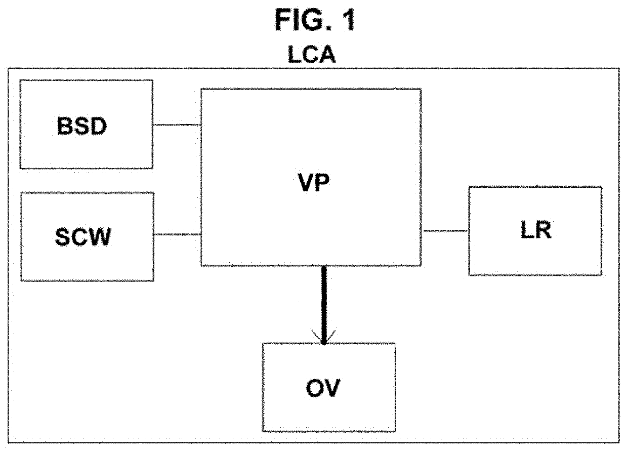
[0053]According to a preferred embodiment, the system comprises the following modules, shown in FIG. 1, which are connected to an Electronic Control Unit (ECU):[0054]Blind Spot Detection (BSD) module: This module detects the presence or absence of vehicles in the near adjacent areas. This module is the basis of the present invention and it will be described in more detail hereinafter, the rest of the modules being optional.[0055]Lane Recognition (LR) module: This module detects lane markings for the adjacent lane, so that it gives information about an area of interest, and it can be used to show free space in adjacent lanes, and also identify possible lane change actions. This LR module is used with the SCW module (described hereinafter) and it is not used with the BSD module.[0056]Side Collision Warning (SCW) module: This module detects and estimates 3D parameters for those objects approaching from rear zone areas. This module can include a Focus of Attention (FOA) module, a fine c...


PUM


Abstract

A method for detecting objects in a vehicle blind spot comprises the following steps:generating a region of interest onto an image taken from one camera placed on one side of the vehicle;generating a top view of the region of interest;detecting an object in the region of interest;determining if the object in the region of interest is a target object; andtriggering a signal if it is determined that there is a target object in the region of interest.

Description

BACKGROUND OF THE INVENTIONField of the Invention[0001]The present invention refers to a method and system for detecting objects in a vehicle blind spot.Description of Related Art[0002]A vehicle blind spot is a lateral zone near the vehicle in which the driver has no vision by any side or rear mirror. When the driver wants to change lanes, the driver cannot see any vehicle in this blind spot, so that side collisions are possible.[0003]Technology helps the driver offering systems for detecting vehicle blind spots, so that the system warns the driver with a visual, acoustic and / or vibrating signal that a vehicle is in the blind spot.[0004]Two side zones may be differentiated: “Left / Right Rear Zone” and “Left / Right Adjacent Zone”. The adjacent zone is the zone which is the closest zone to the vehicle and the rear zone is the zone which is behind the vehicle.[0005]These systems are usually known as “Lane change decision aid systems” (LCDAS). These systems are fundamentally intended to w...

Claims


Application Information

Patent Timeline
IPC IPC(8): G08G1/16B60Q9/00G08G1/052B60R11/00B60R11/04
CPCB60Q9/008B60R11/04B60R2011/0042G08G1/167G08G1/052
Inventor BAUMANN, FLORIANBARTRA, ARIADNA
Owner FICOSA ADAS S L U
Why Eureka
Try Eureka