
Charged Particle Beam Device

Active Publication Date: 2016-08-11
HITACHI HIGH-TECH CORP
View PDF2 Cites 4 Cited by
  • Summary
  • Abstract
  • Description
  • Claims
  • Application Information

AI Technical Summary

Benefits of technology

The present invention provides a cost-effective and efficient way to create a multifunctional charged particle optical system. This system combines the functions of an aberration corrector, a beam deflector, and a beam inclination system to achieve high-speed and high-resolution observation of crystal orientations and the like. The use of a parallel current system eliminates magnetic saturation and hysteresis, and allows for easy analysis and design adjustments of the optical lens. Additionally, beam off-axis adjustment can be used to achieve a beam inclination system of no aberration. These technical effects make the system ideal for use in scanning electron microscope (SEM) and transmission electron microscope (TEM) stereo observation and other applications.

Problems solved by technology

In a focused ion beam system (FIB), an electron beam lithography system (EB), and an electron microscope such as a scanning electron microscope (SEM), a transmission electron microscope (TEM), a scanning transmission electron microscope (STEM) using a charged particle beam, beam blur due to a chromatic aberration, a spherical aberration, and the like have become a limit of their resolution and processing accuracy.
In conventional aberration correction techniques, complex multipole systems are used, and some are commercially available; however, they are expensive, and particularly for simultaneous correction of the chromatic aberration and the spherical aberration, highly advanced design and difficult adjustment have been required.

Method used


Image

  • Charged Particle Beam Device
  • Charged Particle Beam Device
  • Charged Particle Beam Device

Examples


embodiment

[0085]FIG. 12 is a schematic cross-sectional view illustrating an embodiment of a charged particle beam device configured to correct aberration with an electrical triplet configuration. In the embodiment illustrated in FIG. 12, an example is illustrated of using an electrostatic lens as a rotationally symmetric lens, which is low cost and space saving and has high controllability since there is no trajectory rotation function unlike the magnetic field lens. Further, in FIG. 12, in addition to an optical system for reducing an electron source diameter and a diaphragm 13 for determining a beam opening angle, a detection system 14 is included for observation of a sample 15. In particular, the diaphragm 13 facilitates trajectory adjustment by being mobilized or being provided with multiple openings to be selected by a deflector. In addition, a case of the electron beam is described below; however, it is the same in a case of the ion beam.

[0086]An electron beam 7 from an electron source ...


PUM


Abstract

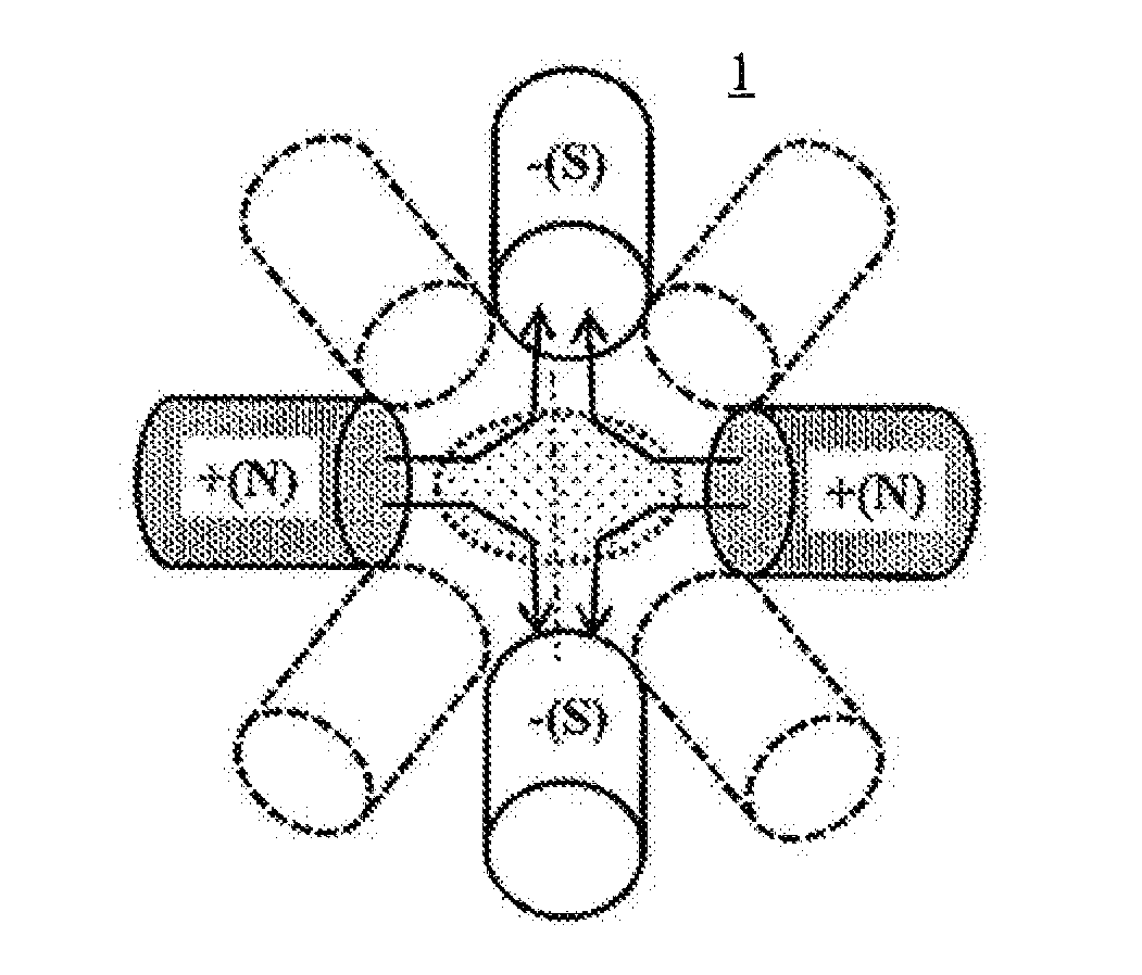
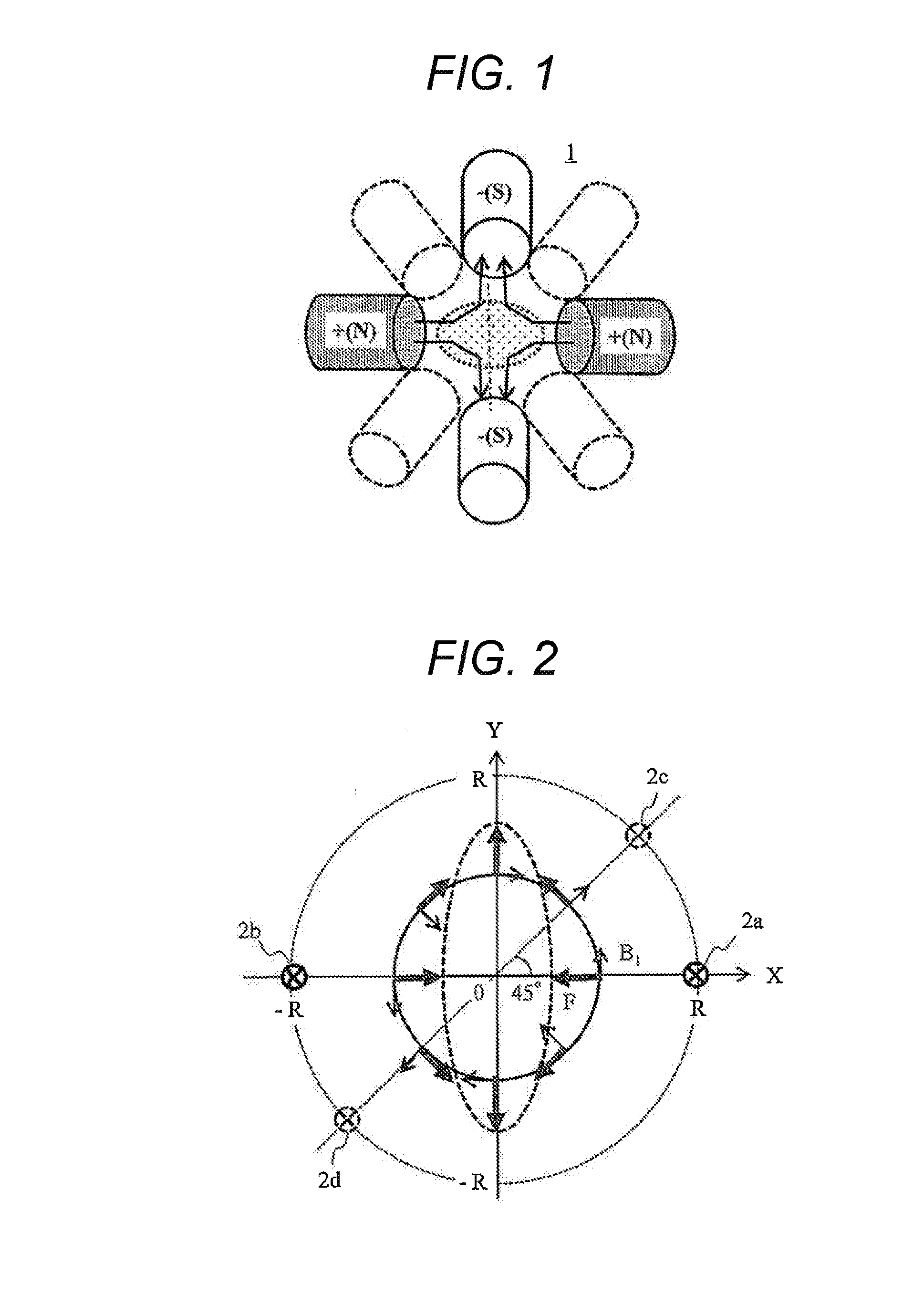
Provided is a multifunctional charged particle beam device capable of inclining a beam with little aberration. The aberration is corrected by forming a local divergent field with a multipole, parallel current lines, or the like, matching the beam axis with the local divergent field via a conventional rotationally symmetric lens, deflector or astigmatism corrector, and counteracting an aberration occurring from another rotationally symmetric convex lens field.

Description

TECHNICAL FIELD[0001]The present invention relates to an aberration correction method used for a charged particle beam device.BACKGROUND ART[0002]In a focused ion beam system (FIB), an electron beam lithography system (EB), and an electron microscope such as a scanning electron microscope (SEM), a transmission electron microscope (TEM), a scanning transmission electron microscope (STEM) using a charged particle beam, beam blur due to a chromatic aberration, a spherical aberration, and the like have become a limit of their resolution and processing accuracy. In conventional aberration correction techniques, complex multipole systems are used, and some are commercially available; however, they are expensive, and particularly for simultaneous correction of the chromatic aberration and the spherical aberration, highly advanced design and difficult adjustment have been required.[0003]In JP 2009-054581 A, a method has been disclosed for forming a multipole field at low cost and having exc...

Claims


Application Information

Patent Timeline
IPC IPC(8): H01J37/153H01J37/12
CPCH01J37/147H01J37/153H01J37/141H01J2237/1534H01J2237/103H01J2237/1532H01J37/12
Inventor SASAKI, YUKOITO, HIROYUKI
Owner HITACHI HIGH-TECH CORP
Learn More