Valve mechanism for internal combustion engine
a technology of internal combustion engine and drive mechanism, which is applied in the direction of valve drive, valve details, valve arrangement, etc., can solve the problems of increasing the inertia force of the swing member which undergoes reciprocating motion, increasing the weight of the parts as well as the size of the entire system, and increasing the wear of the contact portion of the swing member
- Summary
- Abstract
- Description
- Claims
- Application Information
AI Technical Summary
Benefits of technology
Problems solved by technology
Method used
Image


Examples
first embodiment
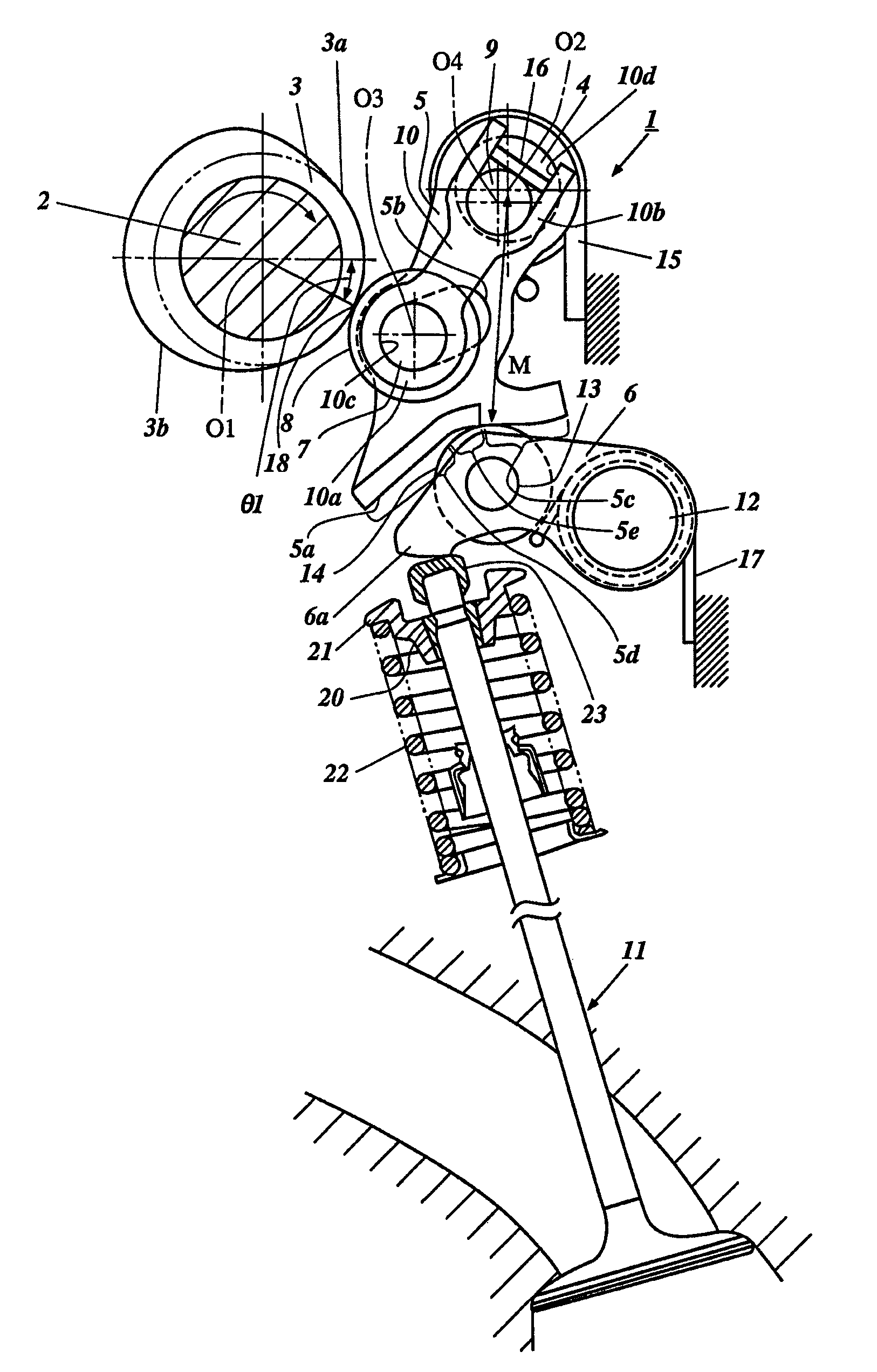
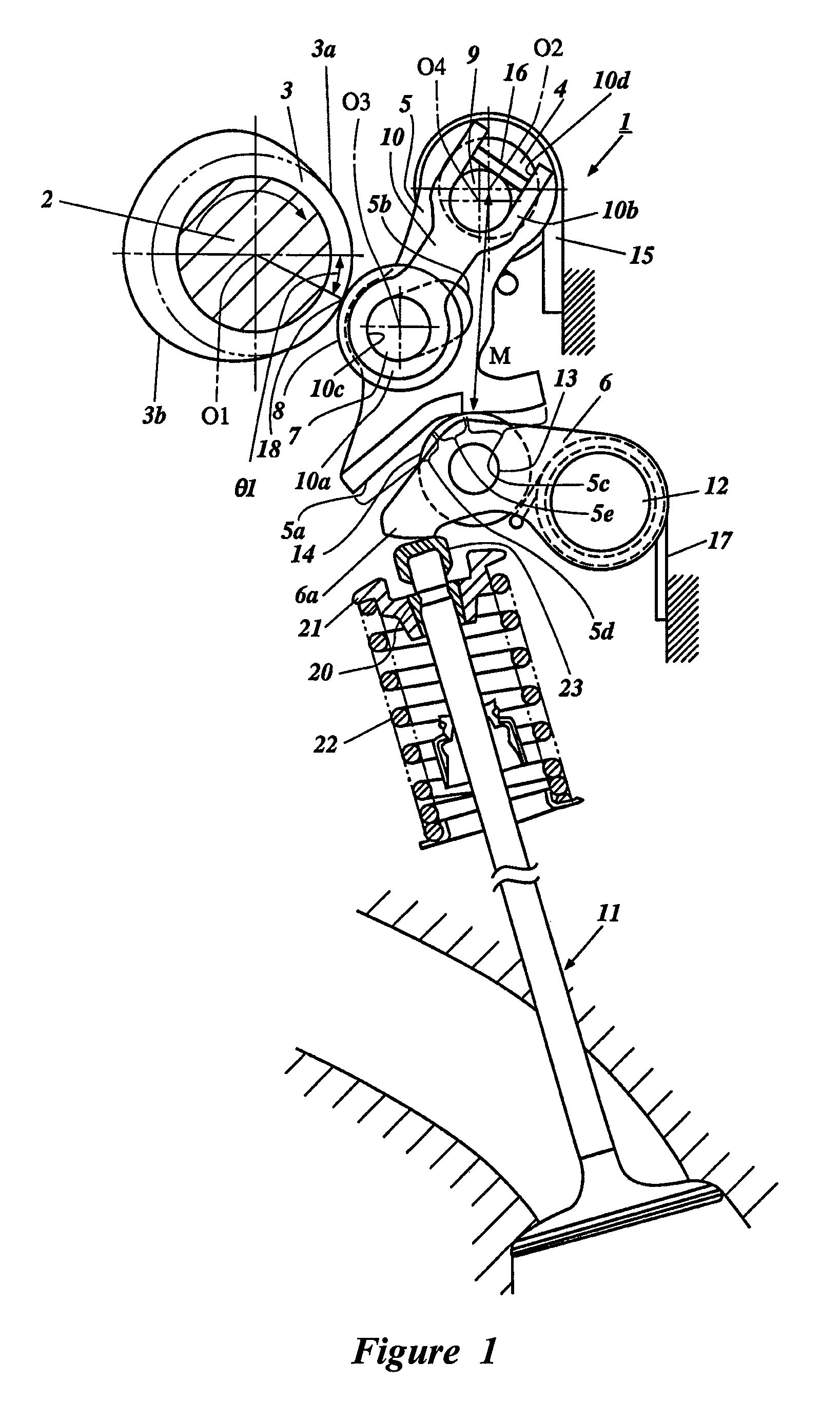
[0029]FIGS. 1 through 5 describe the invention. In FIG. 1, reference numeral 1 denotes a valve drive mechanism for an intake valve 11 of an internal combustion gasoline engine. As shown, the valve drive mechanism 1 can include a valve drive device 2, which in the illustrated embodiment is in the form of a camshaft 2, which is rotated by a crankshaft (not shown) of the internal combustion engine. A rotating cam 3 can be provided on the camshaft 2. A rocking or swinging member support shaft 4 can be provided in parallel to the camshaft 2. A rocking or swinging member 5 can be pivotally supported on the rocking shaft 4 and can be adapted to rock and / or swing through contact with the rotating cam 3. A rocker arm 6 can be provided and arranged such that it is rocked or swung in synchronization with the swing member 5 to open / close the intake valve 11.
[0030]In the embodiments described below, reference will be made to the intake valve 11. However, it should be appreciated that certain fea...
embodiment 1
[0107]Otherwise, this embodiment can be of the same or substantially similar construction and operation as Embodiment 1 of the present invention, so repetitive description will not be repeated.
embodiment 4
[0108]FIGS. 12 and 13 are cross-sectional side views of a valve mechanism according to another In these figures, the intake valve 11 is in a closed position.
[0109]The valve mechanism 1 for an internal combustion engine according this embodiment is capable of adjusting the lift amount or the like of each valve by making the rocking shaft 4 movable to a predetermined position.
[0110]Specifically, as shown in FIG. 12, a roller 33 is arranged on the outer peripheral surface of the rocking shaft 4. The roller 33 is in contact with a guide portion 19a formed in the cylinder head main body 19 for guiding the rocking shaft 4 to a predetermined position. Further, the rocking shaft 4 is provided to the cylinder head main body 19 such that, when the swing member 5 is pressed by a control cam 34 that will be described next, the rocking shaft 4 can move in synchronization with the swing member 12 within a range from a position indicated by the solid line in FIG. 12 to that indicated by the chain...
PUM
 Abstract
Description
Claims
Application Information
 - R&D
- Intellectual Property
- Life Sciences
- Materials
- Tech Scout
- Unparalleled Data Quality
- Higher Quality Content
- 60% Fewer Hallucinations
Browse by: Latest US Patents, China's latest patents, Technical Efficacy Thesaurus, Application Domain, Technology Topic, Popular Technical Reports.
© 2025 PatSnap. All rights reserved.Legal|Privacy policy|Modern Slavery Act Transparency Statement|Sitemap|About US| Contact US: help@patsnap.com