Microchip measurement device

a microchip and measurement device technology, applied in measurement devices, color/spectral properties measurement, instruments, etc., can solve the problems of difficult control of the optical axis, high cost, limited substance to be analyzed, etc., and achieve the effect of predicting the service life of the lamp and keeping the reliability of the determination results high

Inactive Publication Date: 2008-07-15
HORIBA LTD
View PDF12 Cites 0 Cited by
  • Summary
  • Abstract
  • Description
  • Claims
  • Application Information

AI Technical Summary

Benefits of technology

[0015]Therefore, a primary object of the present invention is to devise a microchip analysis device in which, with a relatively simple arrangement, the effect of increasing or decreasing the quantity of light of a discharge lamp of the short arc type can be reduced and in which thus measurement results with high reliability can be obtained.
[0022]In accordance with the invention the following effects are obtained:
[0023](1) By exercising control such that the detection of the quantity of light transmitted by the microchip in the case of determining the fluctuation in the arc is interrupted or stopped, effects due to the fluctuation of the quantity of lamp light on the measurement of decadic extinction can be prevented. A microchip measurement device can be devised in which the decadic extinction is measured with high precision and results with high reliability can be obtained.
[0026](4) By determining the arc fluctuation, the lamp service life can be predicted. The lamp can be replaced without missing the opportunity and the reliability of the determination results can be kept high by the microchip measurement device.

Problems solved by technology

Therefore, in the case of a light source which emits a single wavelength, such as a laser, the substance to be analyzed is limited.
Since control of the optical axis is very difficult in practice and in addition costs are high, implementation is however difficult.

Method used


Image

  • Microchip measurement device
  • Microchip measurement device
  • Microchip measurement device

Examples


Embodiment Construction

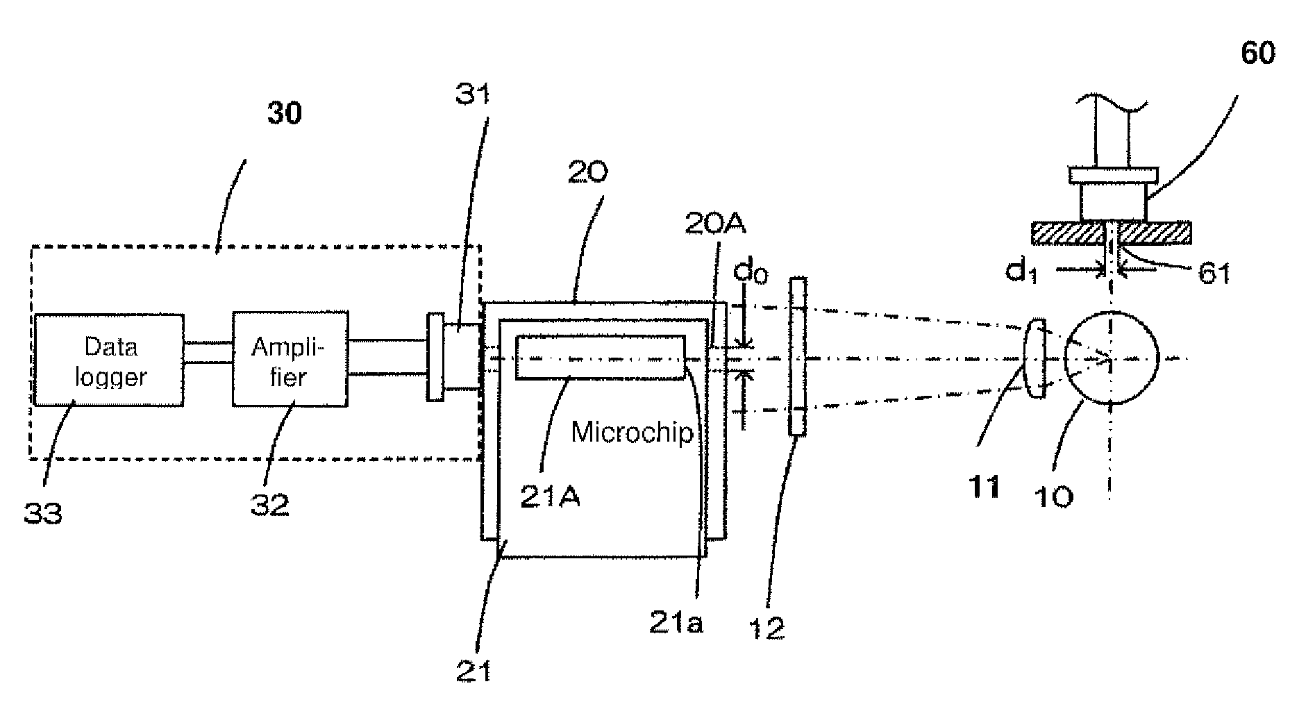
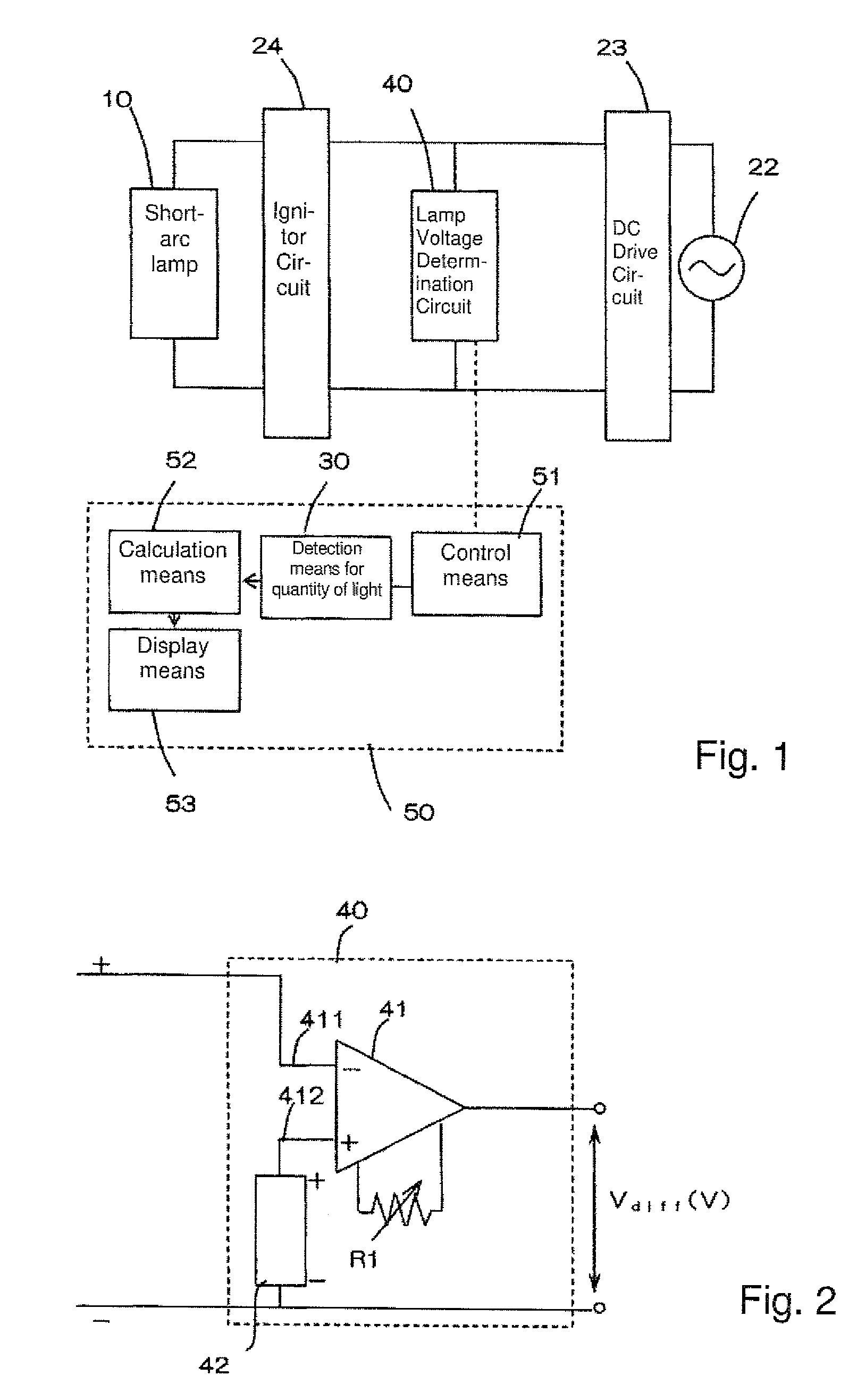
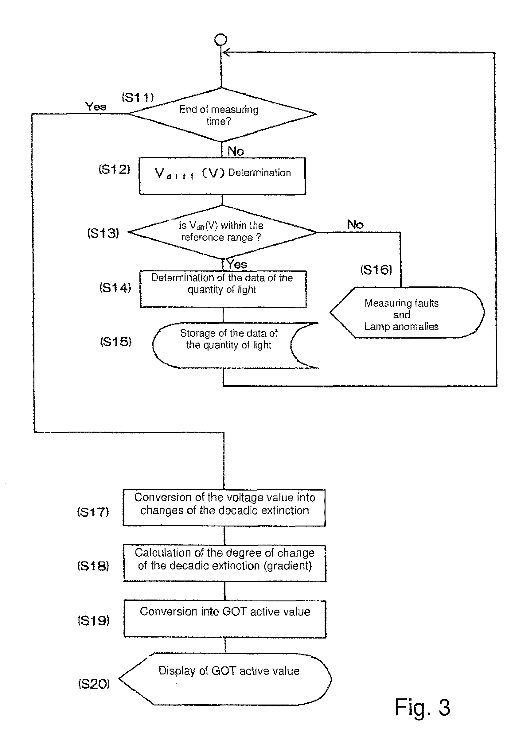
[0036]FIG. 1 is a block diagram of the microchip measurement device in accordance with the invention. FIG. 2 shows an example of a circuit arrangement of a means for determining the arc fluctuation. FIG. 3 shows a flowchart of the invention. FIG. 4 shows an example of a time chart of the arc determination means. Since in the microchip measurement device the arrangement of the optical system is identical to the above described arrangement as shown in FIG. 8, it is described using it.

[0037]The microchip measurement device according to this exemplary embodiment measures the concentration of the component to be detected in a liquid which is to be tested (test object) and with which the microchip is filled, by a process for analysis of decadic extinction. For example, GOT active values are measured in this process.

[0038]In FIG. 1, a direct current driver circuit converts the power from a line current source into a direct current and exercises constant current control.

[0039]In the figure,...


PUM

PropertyMeasurementUnit
rated voltageaaaaaaaaaa
distanceaaaaaaaaaa
wavelengthaaaaaaaaaa

Abstract

A microchip analysis device in which the effect of changes in the quantity of light of a discharge lamp of the short arc type can be reduced and measurement results with high reliability can be obtained is achieved in microchip measurement device which has a light source lamp and a lamp operating device, in which the light from the lamp is transmitted by a fill part for the liquid of the microchip to be tested, and in which the quantity of this transmitted light and based on the data obtained the decadic extinction of the liquid to be tested are measured, a device determines the fluctuation of the quantity of light from the light source lamp. Based on data from this device, a control interrupts or stops the detection of the quantity of the light transmitted by the microchip when the fluctuation is outside a preset range.

Description

BACKGROUND OF THE INVENTION[0001]1. Field of the Invention[0002]The invention relates to a microchip measurement device.[0003]2. Description of Related Art[0004]In various fields such as medical treatments, biology and the like, a process has recently been under increasing development which is called μ-TAS (μ-Total Analysis System) or “Lab on a chip” and in which analyses are performed with high precision and high sensitivity using a microchip and substances are synthesized with high efficiency. For example, μ-TAS is a device in which chemical processes such as pumping, mixing, injections, reactions, extractions, analyses and the like are integrated into one microchip. Since this device can carry out chemical reactions which cannot be performed in chemical facilities with ordinary scales, with high efficiency, it has a potential to become an important tool for carrying out everyday health check-ups and injections and therapies with consideration of different individual body composit...

Claims


Application Information

Patent Timeline
Patent Type & Authority Patents(United States)
IPC IPC(8): G01N21/00
CPCG01N21/274G01N21/33
Inventor MATSUMOTO, SHIGEKIKOSHINDO, TORU
Owner HORIBA LTD
Why Eureka
Try Eureka