Stereoscopic image display device
a display device and stereoscopic technology, applied in the field of stereoscopic image display devices, can solve the problems of reducing the brightness of the observer's eye, and affecting the correct display of colors,
- Summary
- Abstract
- Description
- Claims
- Application Information
AI Technical Summary
Benefits of technology
Problems solved by technology
Method used
Image
Examples
first embodiment
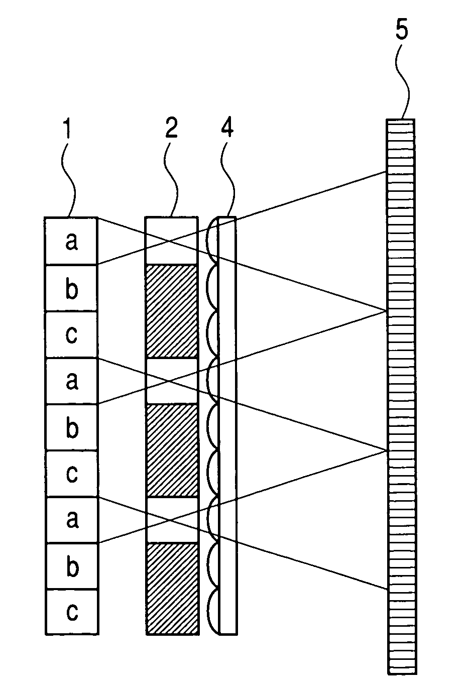
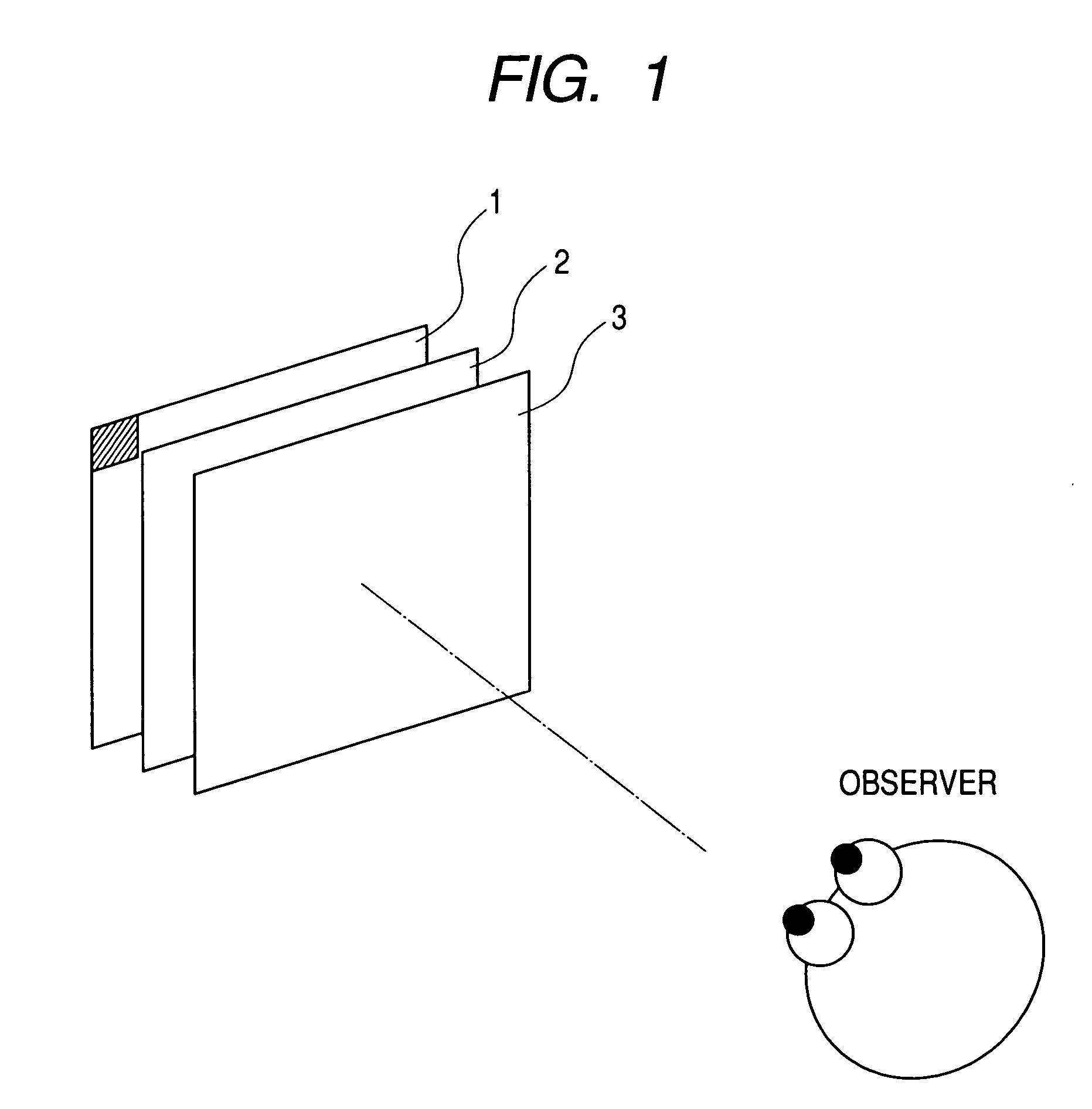
[0107]FIG. 1 is a perspective view explaining the outline of a stereoscopic image display device according to the first embodiment of the present invention. Image display means 1 displays a synthetic image obtained by synthesizing a parallax image. As the image display means 1, an ordinary image display means such as a liquid crystal display and a plasma display and the like can be used. Further, if limited to the reconstruction of a static stereoscopic image, a photograph and a printed matter can be also used. Horizontal directional control means 2 has an optical power in a horizontal direction, and can independently present a plurality of parallax images to each of different directions by giving a directivity in each of desired directions to the image information light including information on each parallax images radiated from the image display means 1. A parallax barrier or a lenticular lens can be used as the horizontal directional control means 2. Longitudinal enlarging means ...
second embodiment
[0134]In the first embodiment as described above, while the example of configuring the horizontal directional control means 2 by the parallax barrier 2-1 was described, it is possible to make the reduction of the image quality less conspicuous by the longitudinal enlarging means 3 in the case where a connection of the mask and the cylindrical lens array is used as the horizontal directional control means 2.
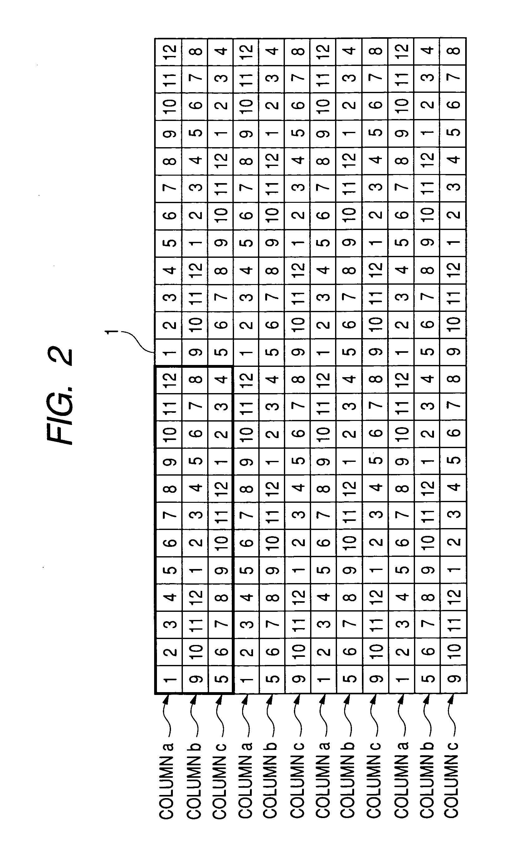
[0135]FIG. 16 shows a mask 2-3 which is a barrier means composing a portion of the horizontal directional control means 2 of the present embodiment. The horizontal width of the slit portion of the mask 2-3 equals to the length of four pixels, and the vertical width equals to one pixel for the image display means 1 which has a pixel arrangement having 12-pixel horizontal period as shown in FIG. 2.
[0136]Further, FIG. 17 shows a cylindrical lens array 2-2 composing a portion of the horizontal directional control means 2 of the present embodiment. The cylindrical lens array 2-2 has co...
third embodiment
[0152]The present embodiment improves the stereoscopic image display device according to the above-described embodiment, and an embodiment for configuring a stereoscopic image display device having a better performance will be described.
[0153]FIG. 26 is a perspective view explaining the outline of the stereoscopic image display device according to the present embodiment. In FIG. 26, in addition to the configuration shown in FIG. 1, the stereoscopic image display device is configured by inserting an optical connecting means 7 so as to optically make a correspondence between each column of the pixel and each region on the horizontal directional control means between image display means 1 and horizontal directional control means 2.
[0154]FIG. 25 shows an example where the beam from the pixel on the image display means 1 enters a non-corresponding region of the horizontal directional control means 2. The beam radiated from a pixel a passes through the slit portion of the corresponding pa...
PUM
 Abstract
Description
Claims
Application Information
 - R&D
- Intellectual Property
- Life Sciences
- Materials
- Tech Scout
- Unparalleled Data Quality
- Higher Quality Content
- 60% Fewer Hallucinations
Browse by: Latest US Patents, China's latest patents, Technical Efficacy Thesaurus, Application Domain, Technology Topic, Popular Technical Reports.
© 2025 PatSnap. All rights reserved.Legal|Privacy policy|Modern Slavery Act Transparency Statement|Sitemap|About US| Contact US: help@patsnap.com


