
Heatsink locking device

a technology of locking device and heat sink, which is applied in the direction of lighting and heating apparatus, semiconductor/solid-state device details, furniture parts, etc., can solve the problems of inconvenient use and the only application of locking device, and achieve the effects of avoiding operating errors, high utilization value, and easy detection

Inactive Publication Date: 2008-07-22
INVENTEC CORP
View PDF5 Cites 7 Cited by
  • Summary
  • Abstract
  • Description
  • Claims
  • Application Information

AI Technical Summary

Benefits of technology

The present invention provides a heatsink-locking device with a separated clamp and bottom base, which can be widely applied to all sizes heatsinks. The device requires no tools during installation and is easy and laborsaving to use. It includes a clamping tool with a guiding part, clamping hooks, and a connecting arm to allow for clamping and unclamping motion. The device is an associated device that can detect if the device has been clamped correctly, avoiding operating mistakes due to human factors. The invention solves the drawbacks of prior art and has a high utilizing value in industries.

Problems solved by technology

However, CPU generates large amount of exothermic heat during highly frequent operation and the high temperature may become a potential factor causing the computer breakdown, therefore a heatsink device is provided to solve this problem.
However, using a screw-locked method to luck up the heatsink is annoying and cause inconvenience for users.
Furthermore, although there are many heatsink locking device provided nowadays that requires no tooling during installation, but because the clamp used to lock the heatsink onto the bottom base is disposed on the bottom base, so one locking device can only be applied to one particular model and size heatsink.
Therefore, to improve the drawbacks from the prior art has become a problem desired to be solved.

Method used


Image

  • Heatsink locking device
  • Heatsink locking device
  • Heatsink locking device

Examples


Embodiment Construction

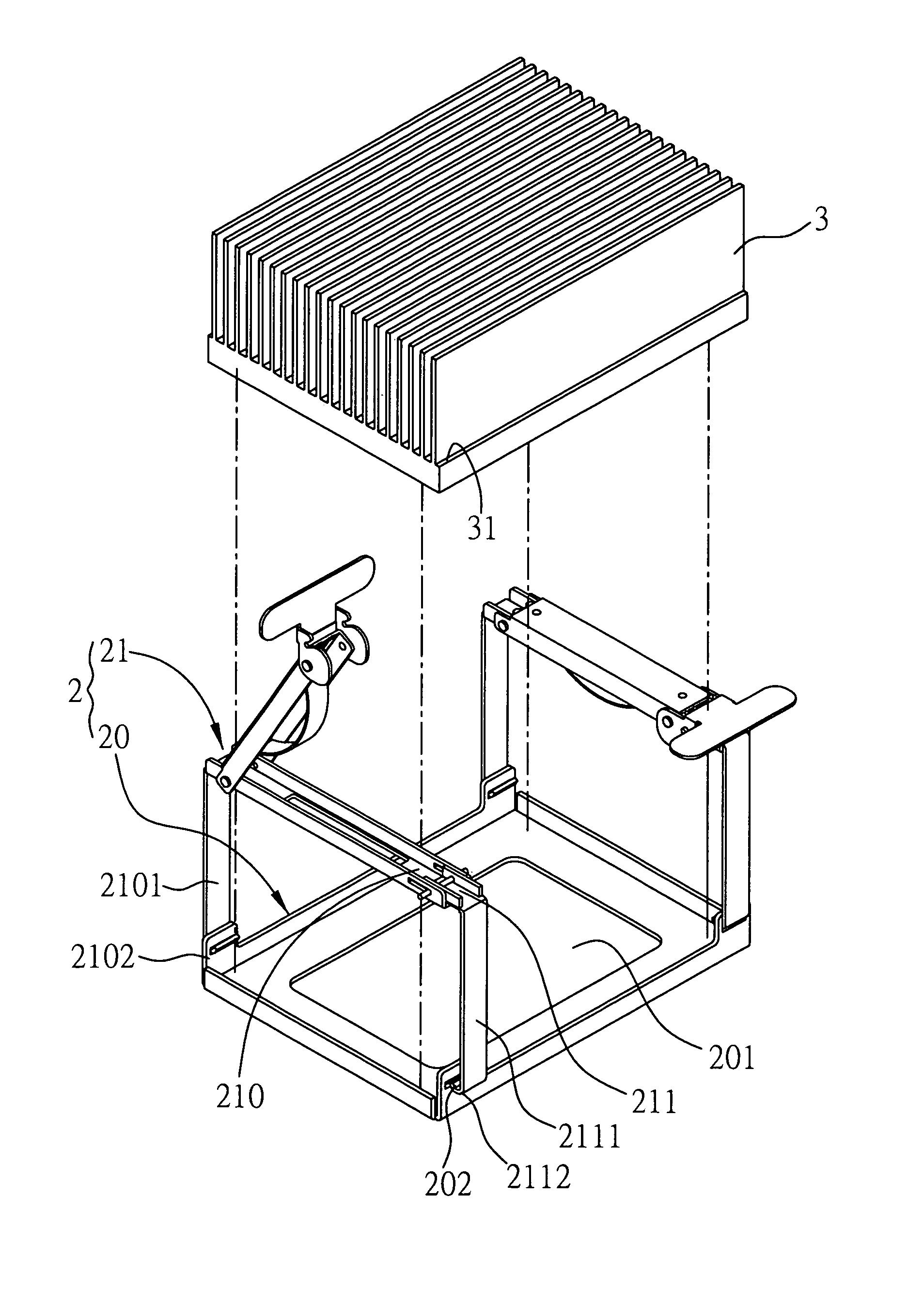
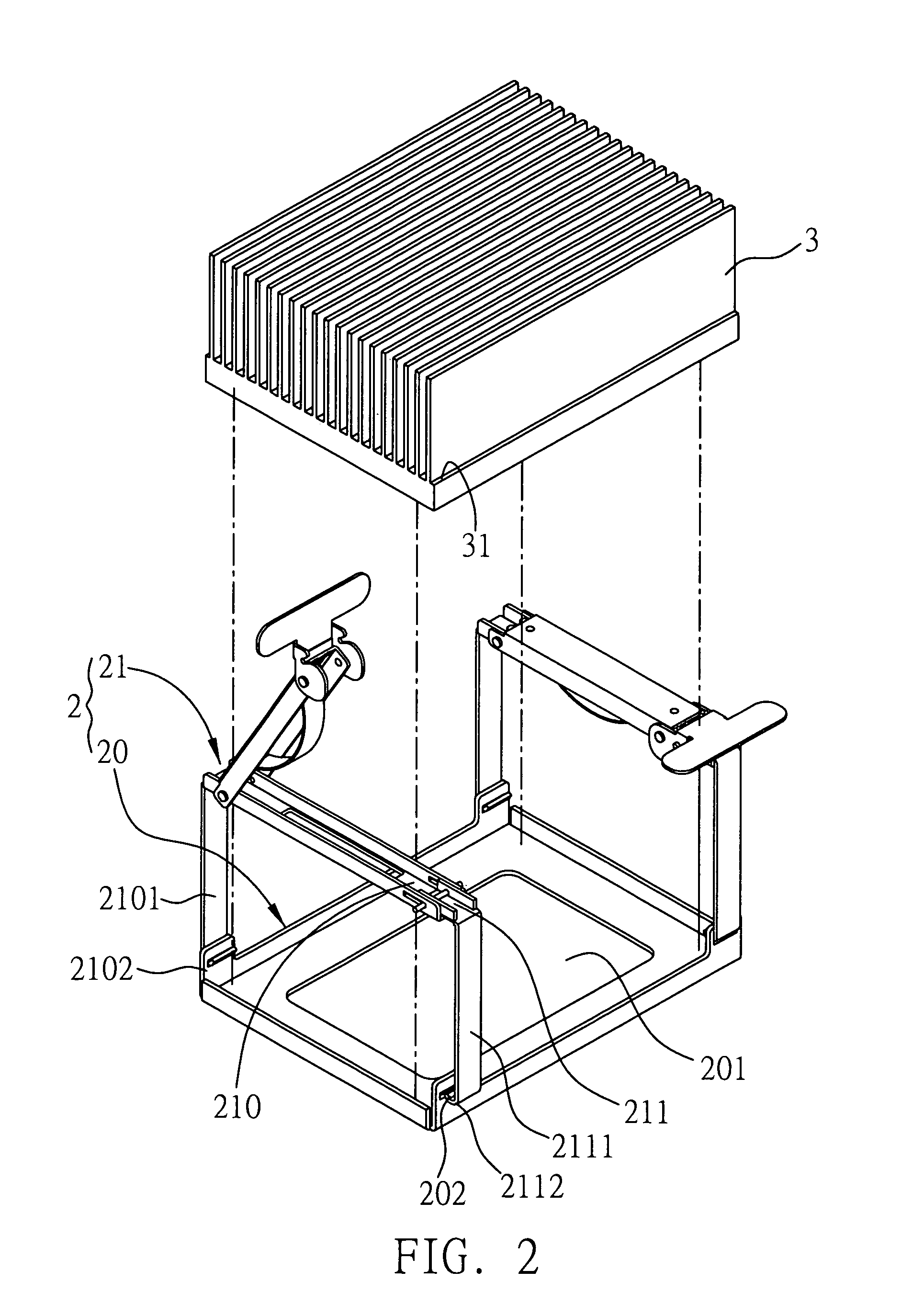
[0020]Referring to FIG. 2, which is a schematic view of an exemplary preferred embodiment of the present invention of a heatsink-locking device. The present invention of a heatsink-locking device 2 is applied to lock a heatsink 3 to a placement surface (not shown in diagram, such as a mainboard) having an exothermic component, and the heatsink 3 has a plurality of heatsink fins 31 and the locking device comprises: a bottom base 20, forms an open hole 201 for disposing the exothermic component and clamping portions 202 in pairs at two opposing lateral sides. A plurality of clamping tools, includes a first board part 210 and a second board part 211 that moves along each other, and bends downwards respectively to form a first extension strip 2101 and a second extension strip 2111 opposite to each other, and then further forms a first joint part 2102 and a second joint part 2112 at the end respectively to joint to the corresponding clamping portions individually and touch to the heatsin...


PUM


Abstract

A heatsink-locking device that is applied to lock a heatsink to a placement surface having an exothermic component, includes a bottom base fixed on the placement surface to dispose and position the heatsink and having an open hole corresponding to the exothermic component and clamping portions at two opposing lateral sides; and a clamping tool for pressing the heatsink and being jointed to the bottom base, the clamping tool including a first board part and a second board part connected to each other with a distance between these two parts being adjustable, a third board part axially connected to the first board part to fix the adjustable distance, a pressing part fixed to the third board part to press the heatsink, and a first joint part and a second joint part disposed at one end of the first and second board parts respectively to be jointed to the clamping portion.

Description

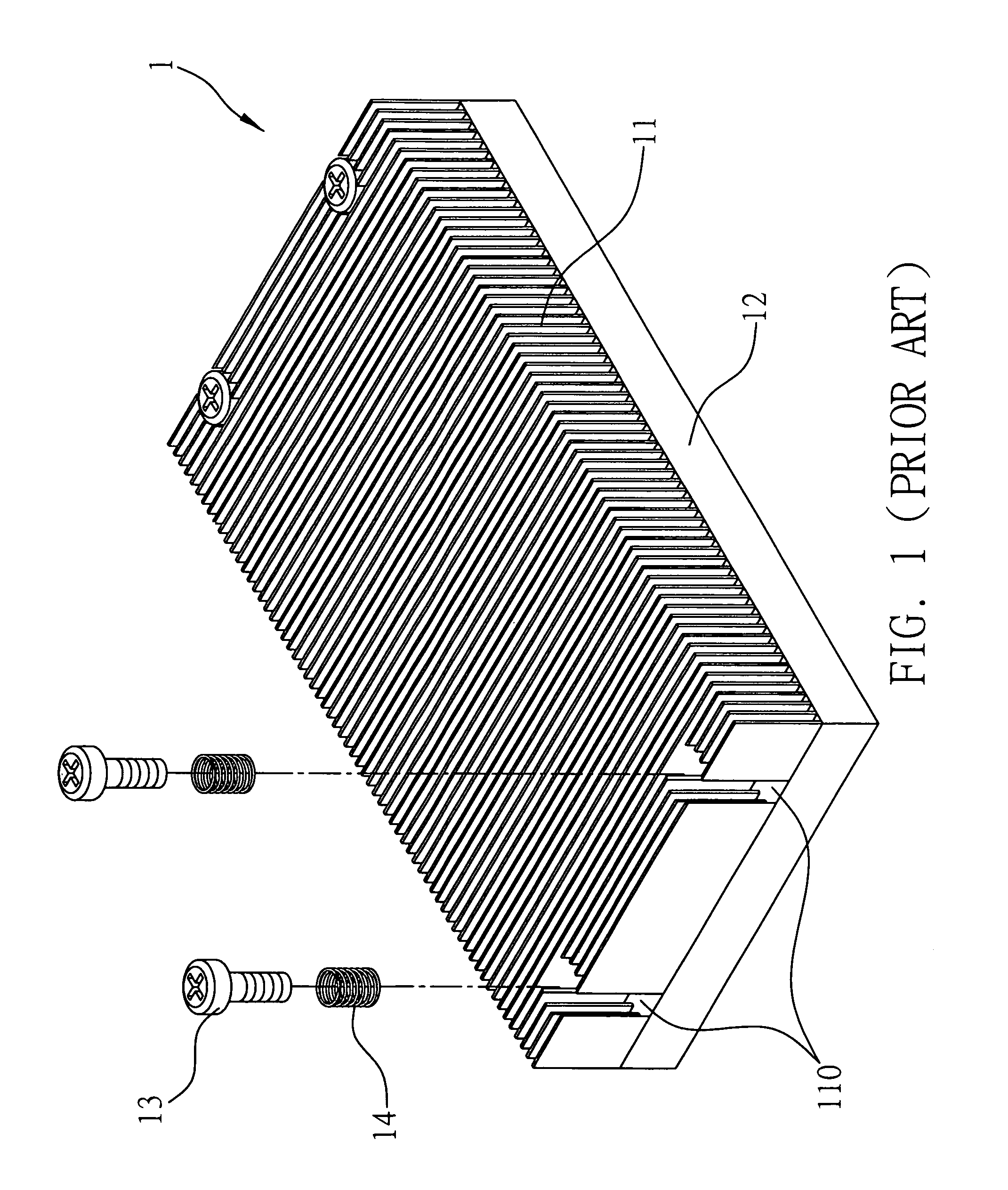
FIELD OF THE INVENTION[0001]The present invention relates to a heatsink-locking device, and, more particularly, to a heatsink-locking device that locks the fin heatsink.BACKGROUND OF THE INVENTION[0002]Central Processing Unit (CPU) is the main part of the computer, providing a processing and a central control function for the computer, which is undoubtedly important. However, CPU generates large amount of exothermic heat during highly frequent operation and the high temperature may become a potential factor causing the computer breakdown, therefore a heatsink device is provided to solve this problem.[0003]As show in FIG. 1, the conventional heatsink device for the CPU to dissipate the heat comprises: heatsink device 1 that is disposed on a frame 12, forms a plurality of heatsink fins 11 for heat dissipation, and also forms open holes 110 on two sides which allows screw 13 going through spring 14 then screw locked on the frame 12; thus the heatsink device 1 can be locked on the frame...

Claims


Application Information

Patent Timeline
Patent Type & Authority Patents(United States)
IPC IPC(8): H05K7/20F28F7/00H01L23/34
CPCH01L23/4093H01L2924/0002Y10T24/44427Y10T24/4447H01L2924/00
Inventor CHEN, WIN-HAW
Owner INVENTEC CORP
Learn More