Injection unit of injection molding machine

a technology of injection molding machine and injection unit, which is applied in the direction of auxillary shaping apparatus, manufacturing tools, ceramic shaping apparatus, etc., can solve the problems of fluctuation of friction force of injection mechanism unit and influence of resin pressure detection by load cell, and achieve high-accuracy resin pressure detection

Active Publication Date: 2008-07-29
FANUC LTD
View PDF15 Cites 0 Cited by
  • Summary
  • Abstract
  • Description
  • Claims
  • Application Information

AI Technical Summary

Benefits of technology

[0013]The screw rotation motor is drawn toward the second member by the tension of the belt run between the pulley shaft mounted on the first member and the screw rotation motor, causing the second member to deform. However, because the first member on which the load detection unit is mounted and the second member are configured as separate units, the first member is not affected by the tension of the belt, thus enabling high-accuracy resin pressure detection.

Problems solved by technology

This belt exerts a force in a radial direction on the pulley provided on the injection screw side, creating moment on the shaft on which the pulley is mounted, causing the force of friction of the injection mechanism unit to fluctuate and affecting the resin pressure detected by the load cell.

Method used


Image

  • Injection unit of injection molding machine
  • Injection unit of injection molding machine
  • Injection unit of injection molding machine

Examples


first embodiment

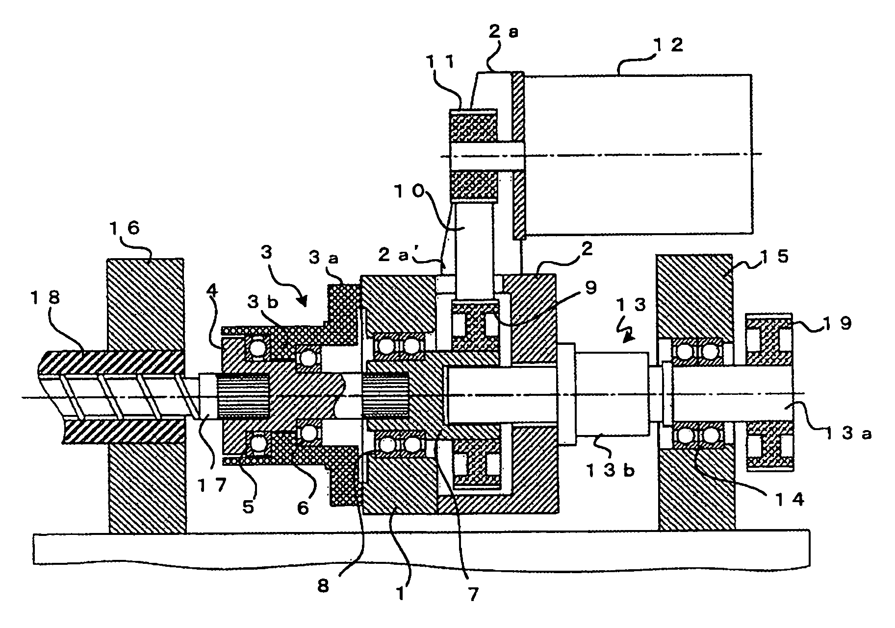
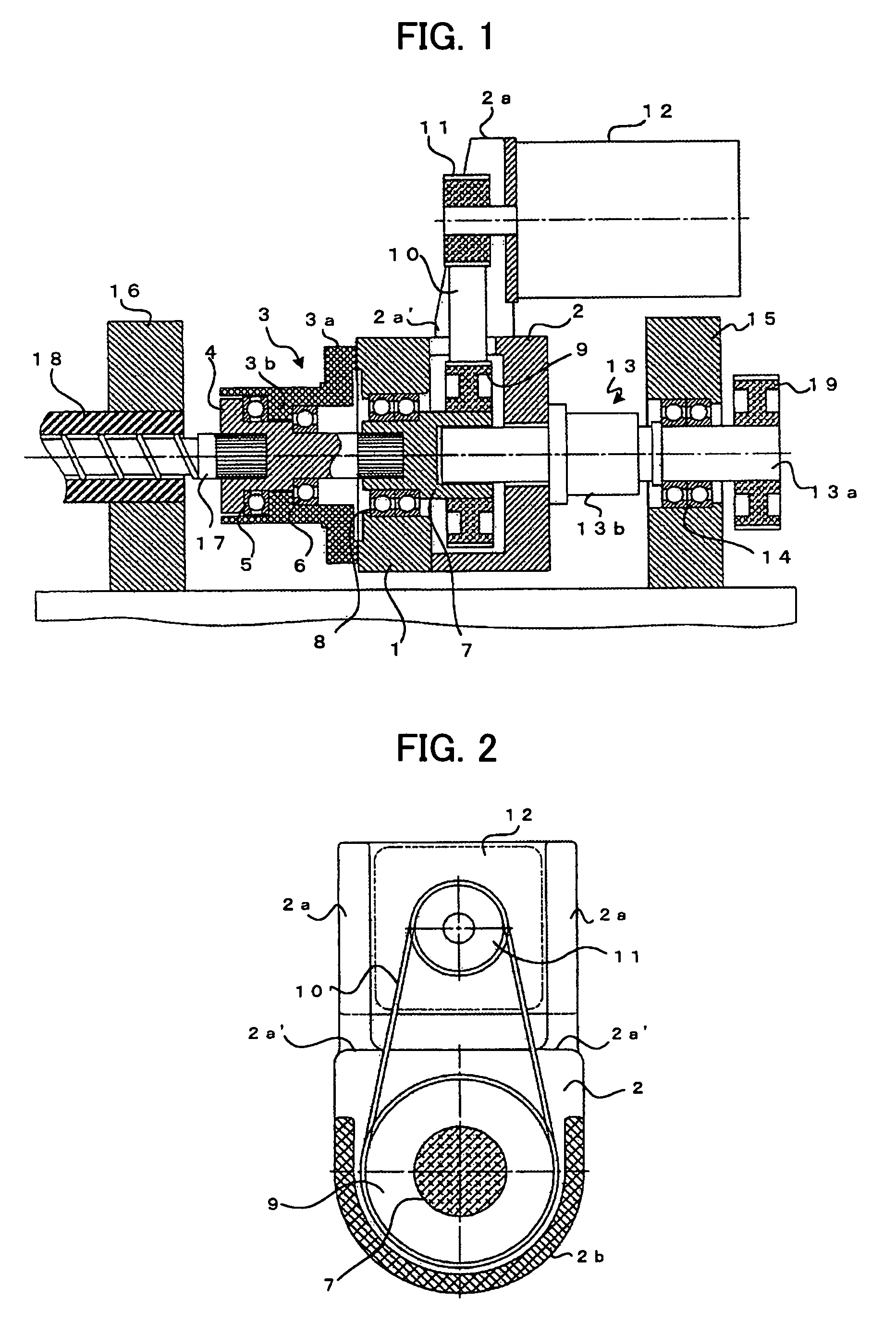
[0018]FIG. 1 is a diagram illustrating an injection unit of the present invention, showing a sectional view cut along a center line thereof.

[0019]An injection screw 17 is inserted into a heating cylinder 18 mounted on a front plate 16, with a rear end shaft fixedly mounted on a rotation-transmitting member 4. The rotation-transmitting member 4 is mounted through bearings 5,6 so as to rotate freely but is unable to move in an axial direction within an inner annular part 3b of a load cell 3 operating as a load detection unit. An outer annular part 3a of the load cell 3 is fixedly mounted on a pusher plate (first member) 1. A pulley shaft 7, on which is mounted a driven pulley 9, is mounted so as to be freely rotatable but axially unmovable on the pusher plate 1 through bearings 8. The pulley shaft 7 and the rotation-transmitting member 4 are connected by connecting means that limit only relative movement in a direction of rotation. In the present embodiment, the pulley shaft 7 and the...

second embodiment

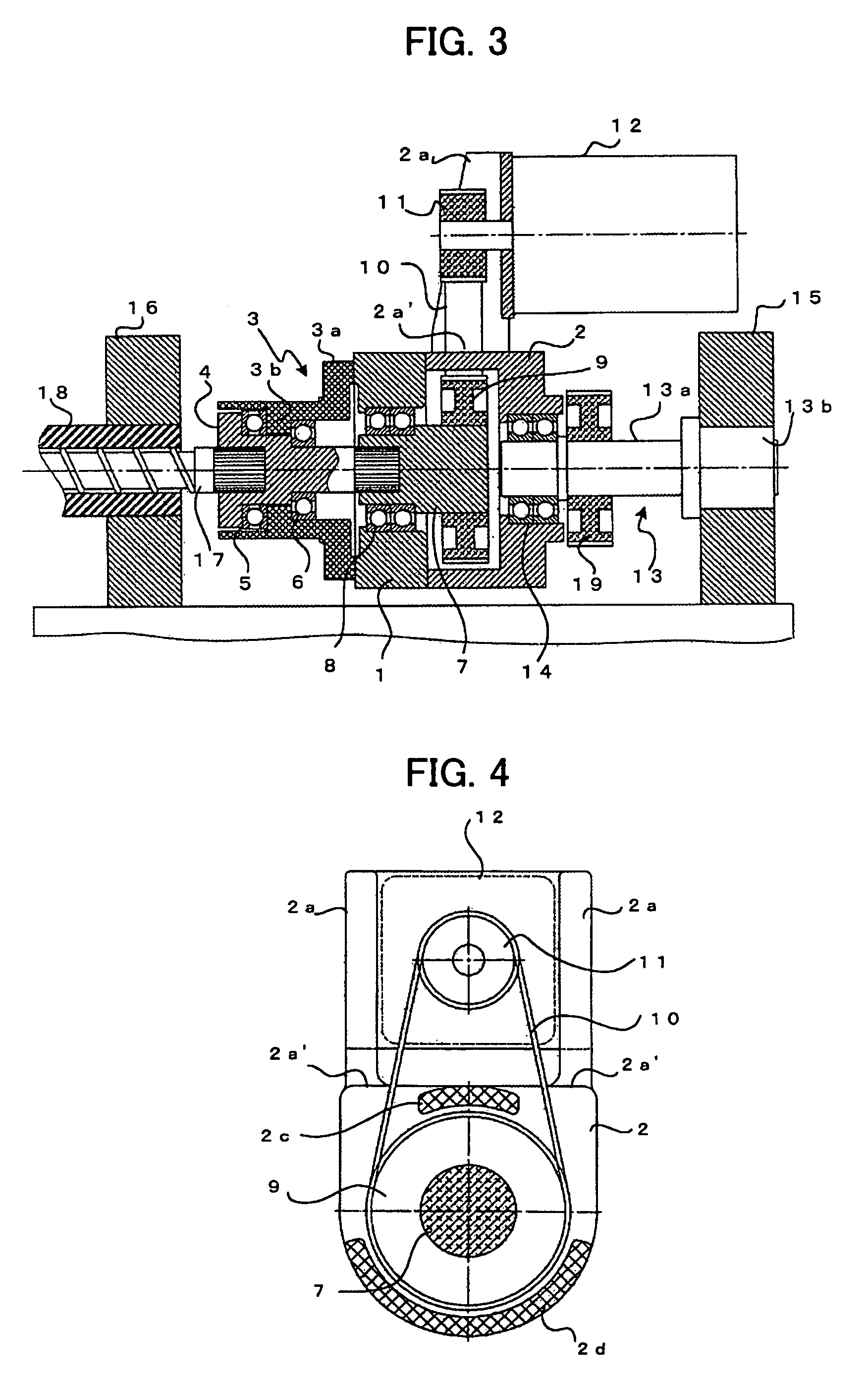
[0030]FIG. 3 is a diagram illustrating an injection unit according to the present invention, showing a sectional view cut along the central part thereof. In addition, FIG. 4, like FIG. 2, is a diagram showing the interface between the pusher plate 1 and the housing 2, as a sectional view cut along a direction vertical to the plane of the paper in FIG. 3 (that is, as seen from the front side of the injection screw 17).

[0031]In the second embodiment of the present invention, only the structure of the thrust force drive means that drives the injection screw 17 axially and the interface between the pusher plate 1 and the housing 2 are different from their counterparts in the first embodiment.

[0032]In the second embodiment, the ball nut 13b of the ball screw / nut mechanism 13 that forms the thrust force drive means is fixedly mounted on the end plate 15, and the threaded part of the ball screw shaft 13a screws into the ball nut 13b. Then, the other end of the ball screw shaft 13a is mount...


PUM

PropertyMeasurementUnit
timeaaaaaaaaaa
displacementaaaaaaaaaa
pressureaaaaaaaaaa

Abstract

The invention provides an injection molding machine injection unit that eliminates adverse effects on the load cell of belt tension due to belt drive. A load cell that detects resin pressure is mounted on a pusher plate and a rotation-transmitting member, on which an injection screw is fixedly mounted, is axially supported by an inner annular part of the load cell. The shaft of a pulley is axially supported on the pusher plate and coupled by splines to the rotation-transmitting member. A screw rotation motor is mounted on motor mounts of a housing mounted on the rear surface of the pusher plate. Tension on a belt run between the pulley and a pulley mounted on the motor output shaft concentrates a force at the base of the motor mounts. However, the housing is separate from the pusher plate and fixedly mounted on the pusher plate at a location other than that occupied by the base of the motor mounts. Therefore, the belt tension does not adversely affect the load cell, thus enabling high-accuracy resin pressure detection.

Description

BACKGROUND OF THE INVENTION[0001]1. Field of the Invention[0002]The present invention relates to an injection molding machine, and more particularly, to an injection unit of an injection molding machine provided with a load detection unit for detecting resin pressure on the injection screw.[0003]2. Description of the Related Art[0004]In an injection unit of an injection molding machine, a screw-type injection unit (that is, a screw-in-line-type injection unit) melts and kneads resin inside a heating cylinder by rotating an injection screw, and further, retracts the injection screw while applying pressure on the resin with the injection screw and measures the melted resin at that retracted position. Thereafter, the injection unit injects melted resin into a mold by advancing the screw.[0005]As a result, it is necessary that the injection unit be provided with a mechanism that rotates the injection screw and a mechanism for driving the injection screw in an axial direction and injecti...

Claims


Application Information

Patent Timeline
Patent Type & Authority Patents(United States)
IPC IPC(8): B29C45/77B29C48/96
CPCB29C45/5008B29C2045/5032
Inventor NISHIMURA, KOICHISHIMA, KOJINAITO, YASUO
Owner FANUC LTD
Why Eureka
Try Eureka