Photoresist coating apparatus and methods

a technology of photoresist coating and coating method, which is applied in the direction of spraying apparatus, photomechanical coating apparatus, electric apparatus, etc., can solve the problems of time-consuming and complex photolithography process, and the difficulty of forming a uniform photoresist layer on the cylindrical reticl

Active Publication Date: 2018-10-23
SEMICON MFG INT (SHANGHAI) CORP
View PDF2 Cites 0 Cited by
  • Summary
  • Abstract
  • Description
  • Claims
  • Application Information

AI Technical Summary

Benefits of technology

[0010]One aspect of the present disclosure includes a photoresist coating apparatus. The photoresist coating apparatus includes a base; and a position platform moving back and forth along a scanning direction on the base. The photoresist coating apparatus also includes an imprinter having a trench configured to hold photoresist and fixed on the position platform; and a photoresist spray nozzle disposed above the imprinter and configured to spray the photoresist into the trench. Further, the photoresist coating apparatus includes a reticle frame configured to install a cylindrical reticle and enable the cylindrical reticle to rotate around a center axis and contact with the imprinter so as to coat the photoresist in the trench on a surface of the cylindrical reticle.
[0010]One aspect of the present disclosure includes a photoresist coating apparatus. The photoresist coating apparatus includes a base; and a position platform moving back and forth along a scanning direction on the base. The photoresist coating apparatus also includes an imprinter having a trench configured to hold photoresist and fixed on the position platform; and a photoresist spray nozzle disposed above the imprinter and configured to spray the photoresist into the trench. Further, the photoresist coating apparatus includes a reticle frame configured to install a cylindrical reticle and enable the cylindrical reticle to rotate around a center axis and contact with the imprinter so as to coat the photoresist in the trench on a surface of the cylindrical reticle.
[0036]Therefore, the precisely controlled position platform 203 may need to be designed with an appropriate shape. In the disclosed embodiments, the precisely controlled position platform 203 is designed as the sidelong “U” shape. Referring to FIG. 2, the first part 23 and the second part 22 of the precisely controlled position platform 203 may be suspended; and a pressure detection unit 209 may be installed between the first part 23 and the second part 22 of the precisely controlled position platform 203. The pressure detection unit 209 may be used to detect the pressure on the first part 23. During a process for coating the photoresist onto the cylindrical reticle 206, when the surface of the cylindrical reticle 206 contacts with the imprinter 204 fixed on the top surface of the first part 23, the pressure generated in the process for coating the photoresist may be detected. According to the value of the pressure, the contact conditions between the cylindrical reticle 206 and the imprinter 204 may be monitored. When the pressure is significantly large or substantially small, the height of the cylindrical reticle 206 may be adjusted to have an appropriate pressure value (pre-determined threshold value); and / or an alarm message may be sent out.
[0010]One aspect of the present disclosure includes a photoresist coating apparatus. The photoresist coating apparatus includes a base; and a position platform moving back and forth along a scanning direction on the base. The photoresist coating apparatus also includes an imprinter having a trench configured to hold photoresist and fixed on the position platform; and a photoresist spray nozzle disposed above the imprinter and configured to spray the photoresist into the trench. Further, the photoresist coating apparatus includes a reticle frame configured to install a cylindrical reticle and enable the cylindrical reticle to rotate around a center axis and contact with the imprinter so as to coat the photoresist in the trench on a surface of the cylindrical reticle.
[0081]Further, after forming the patterned photoresist, mask patterns may be formed by etching the to-be-etched layer using the patterned photoresist as a mask. The to-be-etched layer may be etched by any appropriate process, such as a dry etching process, or a wet etching process, etc. The cylindrical reticle with the mask patterns may be subsequently used for obtaining patterns on substrates by a photolithography process.
[0023]Further, as shown in FIG. 1, the photoresist coating apparatus may also include a reticle frame 207. The reticle frame 207 may be used to install a cylindrical reticle 206; and to drive the cylindrical reticle 206 to rotate around a central axis, i.e., the central axis of the cylindrical reticle 206. The reticle frame 207 may also be used to control the position and movement of the cylindrical reticle 206 such that the surface of the cylindrical reticle 206 may contact with the top surface of the imprinter 204.

Problems solved by technology

The complex and time-consuming photolithography processes of the semiconductor manufacturing are mainly performed by corresponding exposure apparatus.
However, how to form a uniform photoresist layer on the cylindrical reticle may be still a challenge.

Method used


Image

  • Photoresist coating apparatus and methods
  • Photoresist coating apparatus and methods
  • Photoresist coating apparatus and methods

Examples


Embodiment Construction

[0016]Reference will now be made in detail to exemplary embodiments of the invention, which are illustrated in the accompanying drawings. Wherever possible, the same reference numbers will be used throughout the drawings to refer to the same or like parts.

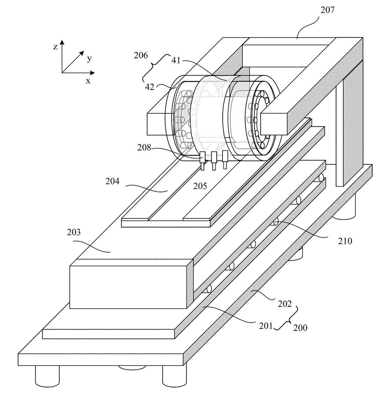
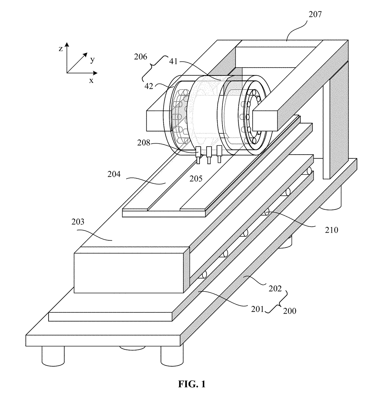
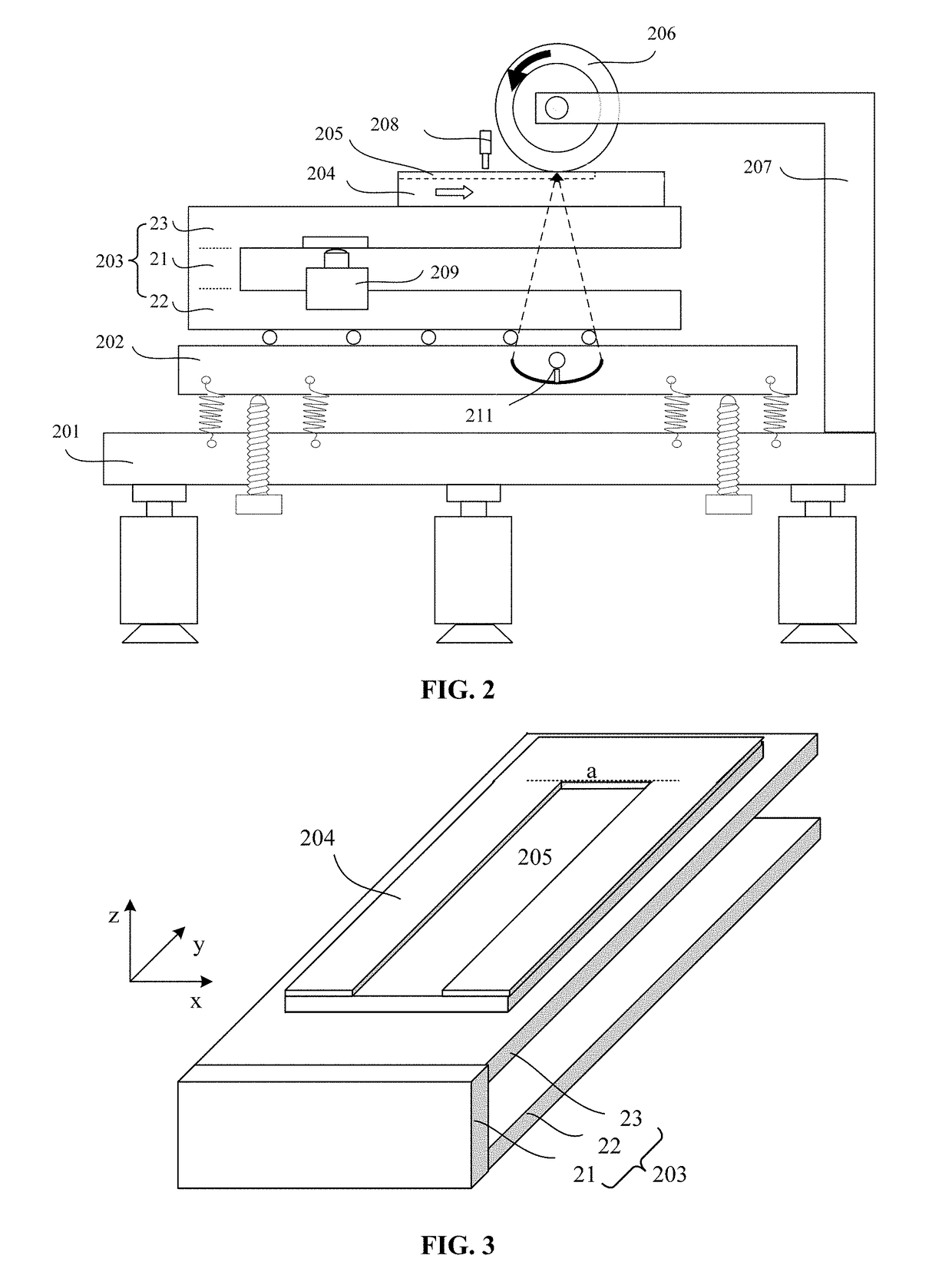
[0017]FIGS. 1˜4 illustrate structures of a photoresist coating apparatus for a cylindrical reticle consistent with the disclosed embodiments.

[0018]As shown in FIG. 1, the photoresist coating apparatus may include a base 200 and a precisely controlled position platform 203 on the base 200. The precisely controlled position platform 203 may move back and forth along a scanning direction on the base 200.

[0019]Referring to FIG. 1, the base 200 may include an optical vibration isolated base platform 201 and a precisely controlled leveling platform 202. The precisely controlled leveling platform 201 may be on the optical vibration isolated base platform 202; and the precisely controlled position platform 203 may be on the precisely contr...


PUM

PropertyMeasurementUnit
depthaaaaaaaaaa
surface roughnessaaaaaaaaaa
heightaaaaaaaaaa

Abstract

A photoresist coating apparatus is provided. The photoresist coating apparatus includes a base; and a position platform moving back and forth along a scanning direction on the base. The photoresist coating apparatus also includes an imprinter having a trench configured to hold photoresist and fixed on the position platform; and a photoresist spray nozzle disposed above the imprinter and configured to spray the photoresist into the trench. Further, the photoresist coating apparatus includes a reticle frame configured to install a cylindrical reticle and enable the cylindrical reticle to rotate around a center axis and contact with the imprinter so as to coat the photoresist in the trench on a surface of the cylindrical reticle.

Description

CROSS-REFERENCES TO RELATED APPLICATIONS[0001]This application claims the priority of Chinese patent application No. 201310222164.4, filed on Jun. 5, 2013, the entirety of which is incorporated herein by reference.FIELD OF THE INVENTION[0002]The present invention generally relates to the field of semiconductor manufacturing technology and, more particularly, relates to photoresist coating apparatus and photoresist coating methods thereof.BACKGROUND[0003]A photolithography process, transferring patterns on a mask to a substrate by an exposure process, is an important process of the semiconductor manufacturing technology. The photolithography process is a core step in the manufacturing of large scale integrations (LSIs). The complex and time-consuming photolithography processes of the semiconductor manufacturing are mainly performed by corresponding exposure apparatus. Further, the development of the photolithography technology or the improvement of the exposure apparatus are mainly f...

Claims


Application Information

Patent Timeline
Patent Type & Authority Patents(United States)
IPC IPC(8): H01L21/027B05B12/12G03F7/16
CPCG03F7/16B05B12/12
Inventor LIU, YANGWU, QIANGHU, HUAYONG
Owner SEMICON MFG INT (SHANGHAI) CORP
Why Eureka
Try Eureka