
Electronic pen

a technology of electronic pen and pen body, applied in the field of electronic pen, can solve the problems of inability to accurately the hammer movement of the inserting pen, and the limitation of the accurate detection of the varying pen pressure in multiple distinct stages, so as to facilitate the refilling of the lead, detect the pen pressure, and high accuracy

Active Publication Date: 2019-02-26
WACOM CO LTD
View PDF16 Cites 0 Cited by
  • Summary
  • Abstract
  • Description
  • Claims
  • Application Information

AI Technical Summary

Benefits of technology

The patent is about an electronic pen that can be refilled with lead from a mechanical pencil. The pen has a detector that can accurately detect the pressure it is used with. This allows for easy refilling and high accuracy detection of pen pressure.

Problems solved by technology

In the case of an electronic pen with the mechanical pencil function added thereto, however, the pen pressure detector disposed on the axis would obstruct the insertion of the lead or hamper the movement of the inserted lead to the pen tip.
Therefore, the annular pen pressure detector provided around the axis cannot receive the axial displacement of the lead as it is, and cannot detect the pen pressure accurately.
For this reason, there is a limitation to accurate detection of the varying pen pressure in multiple distinct stages.
However, if the pen pressure detector is provided on the axis, the insertion and movement of the lead would be obstructed, as aforementioned.
Alternatively, there is needed a laborious operation of taking out an inside mechanism from a casing of the electronic pen, detaching a lead delivering mechanism, for example, from a tip portion, inserting the lead into a lead accommodating section, re-attaching the lead delivering mechanism, and returning the inside mechanism into the casing.
This results in worsening of utility of the electronic pen.
In addition, the knocking mechanism for delivering the lead should be provided taking into account the position of the pen pressure detector, which may complicate the configuration of the electronic pen.

Method used


Image

  • Electronic pen
  • Electronic pen
  • Electronic pen

Examples


modification 1

Case of One Pen Pressure Detector

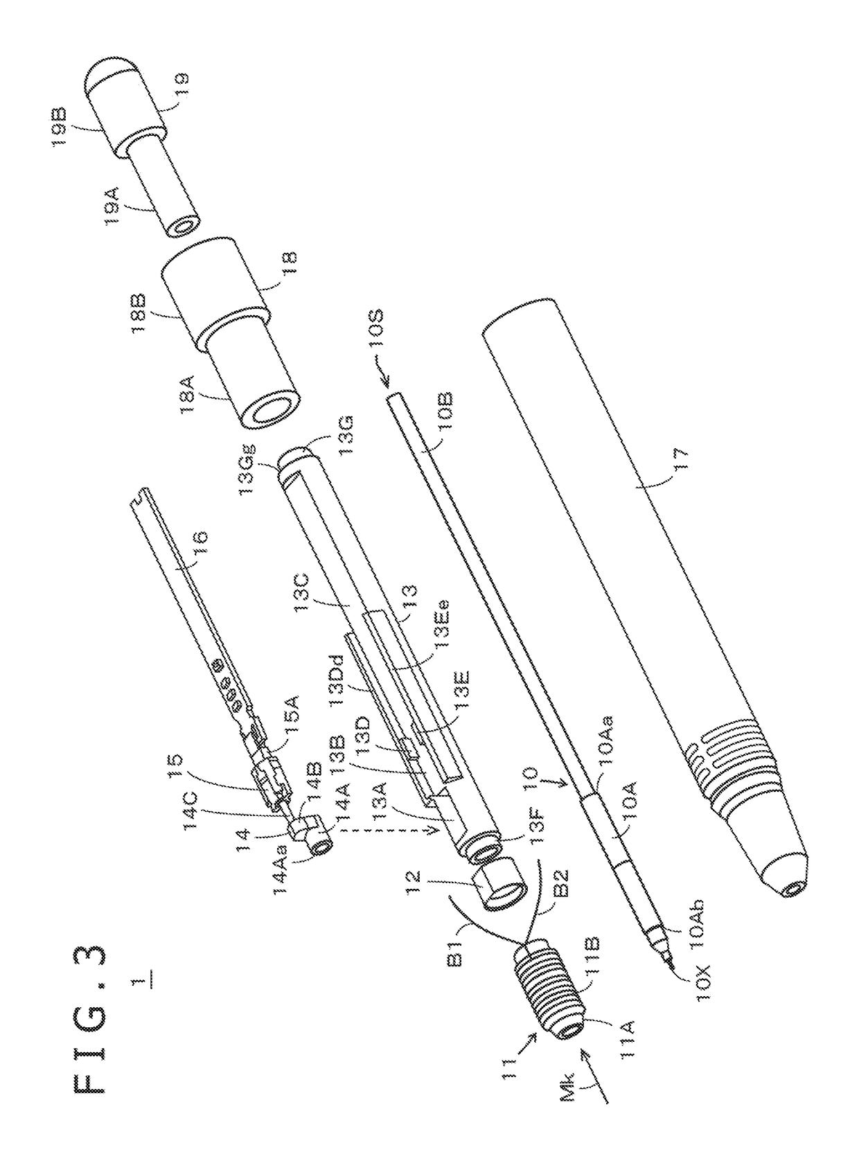
[0076]FIG. 7A illustrates an electronic pen 1A as a modification of the electronic pen 1 wherein a pen pressure in the case of writing and a pressure in the case of using an eraser are detected by one pen pressure detector 15. In FIG. 7A, those parts configured in the same manner as in the electronic pen 1 in the embodiment described above referring to FIGS. 3 to 5B are denoted by the same reference symbols as used above, and detailed descriptions of those parts are omitted. In addition, while FIG. 7A depicts inside configuration parts accommodated in an outer casing, the configuration inclusive of the outer casing will be described as the electronic pen 1A for convenience of explanation.

[0077]The electronic pen 1A according to the modification illustrated in FIG. 7A also has a mechanical pencil function. Therefore, the writing unit 10 including the first portion 10A and the second portion 10B, the core section 11 including the ferrite core 11A and t...

modification 2

Case of Two Pen Pressure Detectors

[0093]FIG. 7B illustrates an electronic pen 1B as a modification of the electronic pen 1, wherein a pen pressure detector for detecting a pen pressure in the case of writing and a pressure detector for detecting a pressure in the case of using an eraser are used. In FIG. 7B, those parts configured in the same manner as in the electronic pen 1 in the embodiment described above referring to FIGS. 3 to 5B and those parts configured in the same manner as in the electronic pen 1A of the modification described above referring to FIG. 7A are denoted by the same reference symbols used above, and detailed descriptions of those parts are omitted. In addition, while FIG. 7B depicts inside configuration parts accommodated in an outer casing, the configuration inclusive of the outer casing will be described as the electronic pen 1B for convenience of explanation.

[0094]The electronic pen 1B in the modification depicted in FIG. 7B is also provided with a mechanica...


PUM


Abstract

A second portion of a writing device is caused to penetrate a through-hole of a tubular portion of a pen pressure transmitter, starting from a first end of the second portion of the writing device, and the tubular portion abuts a surface of a first portion of the writing device that faces the second portion of the writing device. When a pen pressure is exerted on the first portion of the writing device, the pen pressure also is exerted on the tubular portion of the pen pressure transmitter abutting the surface of the first portion of the writing device that faces the second portion of the writing device. The pen pressure is transmitted through the pen pressure transmitter to a pen pressure detector disposed at a position spaced apart from the writing device.

Description

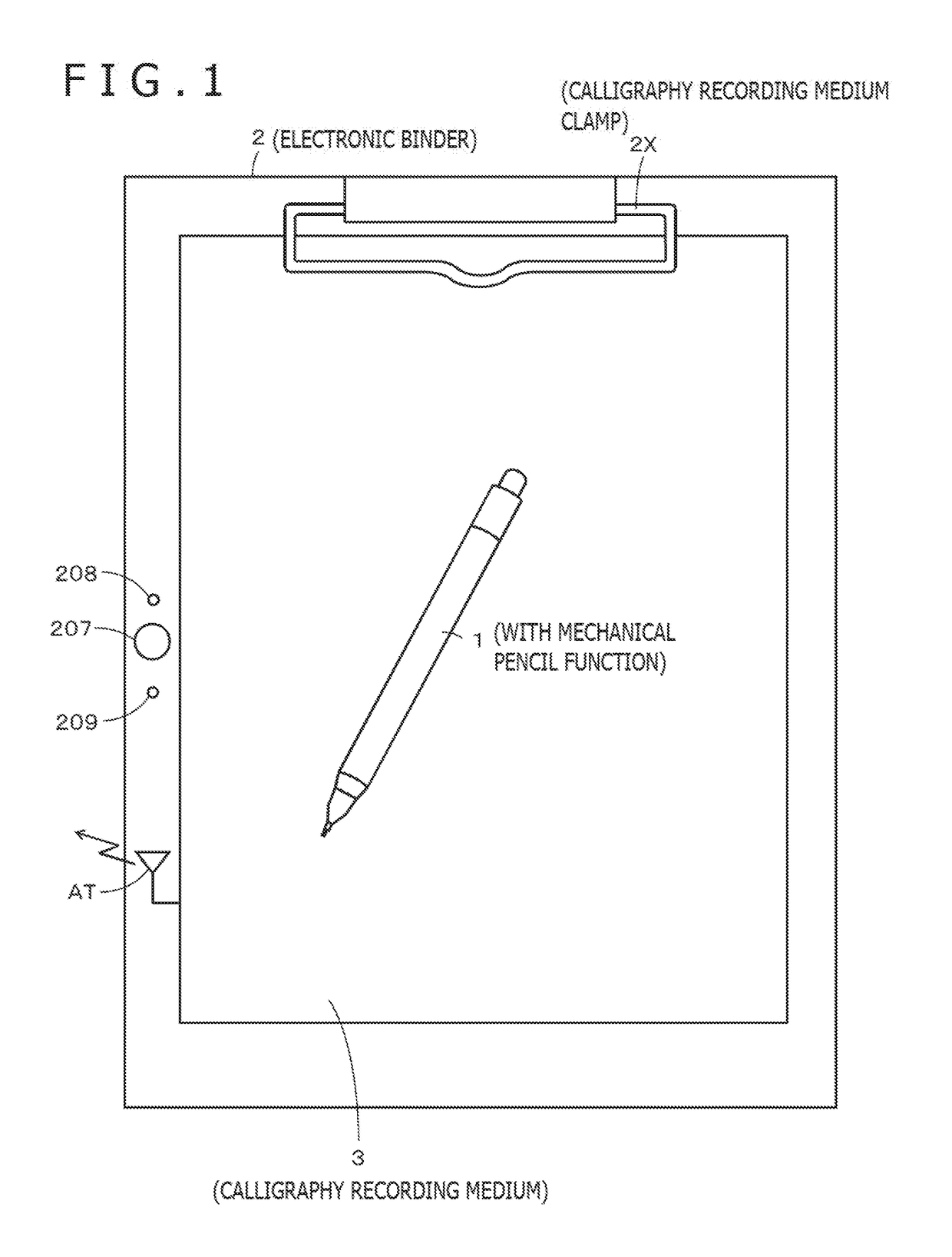
BACKGROUNDTechnical Field[0001]The present disclosure relates to an electronic pen which is a pen-type position indicator to be used with a position detecting device.Description of Related Art[0002]An electronic pen is grasped by a user, and used for indicating a position on a sensor of a position detecting device. The position indicated on the sensor by the electronic pen is detected by the position detecting device, through transfer of a position detection signal between the electronic pen and the sensor, based on, for example, an electromagnetic induction system or a capacitance system. In recent years, there have been realized electronic pens which are provided with a refill of a ball-point pen or a writing unit of a mechanical pencil. The use of such an electronic pen makes it possible to leave calligraphy (written characters and / or drawn figures) on a sheet of paper disposed on the sensor, and, simultaneously, to receive an input of calligraphic data corresponding to the calli...

Claims


Application Information

Patent Timeline
Patent Type & Authority Patents(United States)
IPC IPC(8): G06F3/046G06F3/038G06F3/0354G06K9/24B43K21/16
CPCG06F3/03545G06K9/24G06F3/0383B43K21/16B43K27/00G06F3/046
Inventor TANAKA, KOHEININOMIYA, KENICHI
Owner WACOM CO LTD
Learn More