Adaptive clock-less equalizer circuit

a clockless equalizer and circuit technology, applied in the field of equalization of signals in circuits, can solve problems such as fiber length, and achieve the effect of easing the scaling of equalizers and increasing speeds

Inactive Publication Date: 2008-07-29
PLEXUS NETWORKS
View PDF5 Cites 2 Cited by
  • Summary
  • Abstract
  • Description
  • Claims
  • Application Information

AI Technical Summary

Benefits of technology

[0006]The advantage of this method is that it does not require the integration of the clock recovery on the same IC, which avoids the known issues with the equalizer and the phase locked loop interaction for transversal filters (since they both try to converge at the same time). This also eases the scaling of the equalizer to higher speeds as the redesign of the CDR is not required. The present invention makes possible the advantages of providing an adaptive equalizer for equalizing high-speed data signals and of providing a digitally controlled adaptive equalizer which can be widely tuned and adjusted for various applications.

Problems solved by technology

For a given data frequency, these impairments limit the length of the fiber that can be used for transmission of the data, and thus require equalization.

Method used


Image

  • Adaptive clock-less equalizer circuit
  • Adaptive clock-less equalizer circuit
  • Adaptive clock-less equalizer circuit

Examples


Embodiment Construction

[0010]The present invention relates generally to equalization of signals in a circuit. The following description is presented to enable one of ordinary skill in the art to make and use the invention and is provided in the context of a patent application and its requirements. Various modifications to the preferred embodiment and the generic principles and features described herein will be readily apparent to those skilled in the art. Thus, the present invention is not intended to be limited to the embodiment shown but is to be accorded the widest scope consistent with the principles and features described herein.

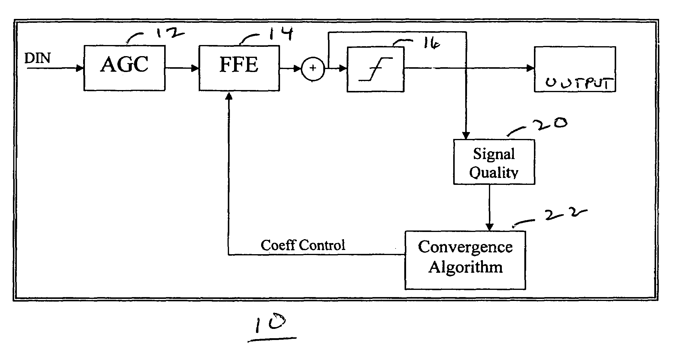
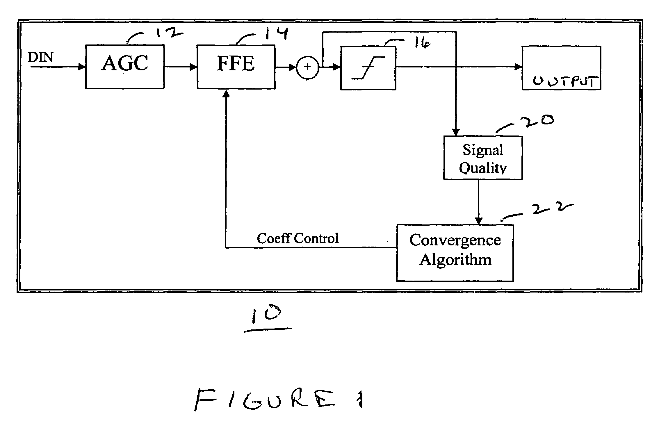
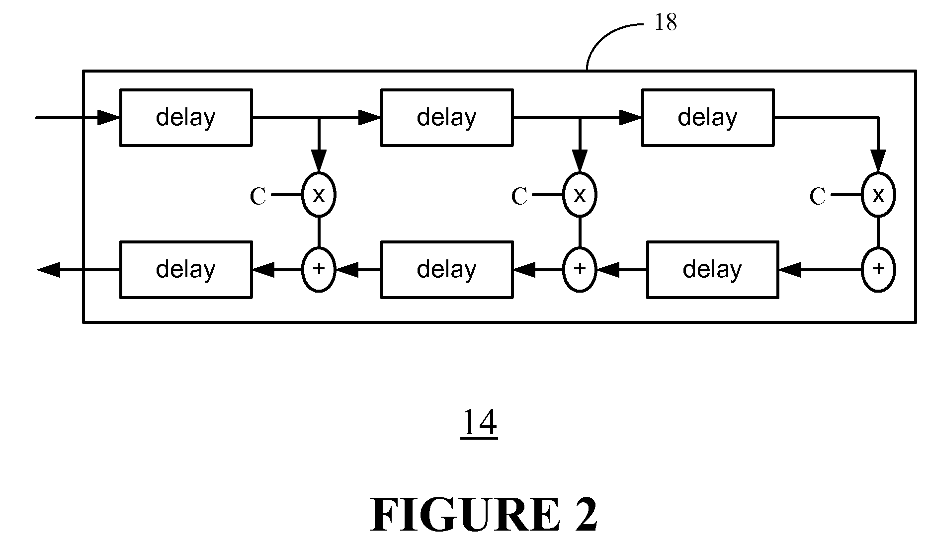
[0011]FIG. 1 is a top level diagram of an adaptive equalizer 10 in accordance with the present invention. Din is the data input of the equalizer 10. The data is provided to an Analog Gain Control (AGC) 12, so that any DC loss can be adjusted and proper signal amplitude obtained. Next, the signal is fed into a Feed Forward Equalizer (FFE) 14 (per description in U.S. patent app...


PUM


Abstract

A system and method for equalizing a signal is provided. In one implementation, the method includes generating a partially equalized signal from an input signal based on a plurality of coefficients associated with a feed-forward equalizer (FFE); generating decoded bit values based on the partially equalized signal, the decoded bit values being an equalized output signal; measuring error in the partially equalized signal; and adjusting the coefficients associated with the feed-forward equalizer (FFE) based on the error measured in the partially equalized signal. Values of the coefficient are not used to adjust of the coefficients associated with the feed-forward equalizer (FFE).

Description

RELATED APPLICATION[0001]This application is related to U.S. patent application Ser. No. 10 / 679,107, entitled “Low-Power, High-Frequency Finite Impulse Finite Response (FIR) Filter and Method of Use,” and filed on Oct. 2, 2003.FIELD OF THE INVENTION[0002]The present invention relates generally to equalization of signals in a circuit.BACKGROUND OF THE INVENTION[0003]Adaptive equalizer systems determine and provide equalizations required for a received waveform to ultimately resemble the originally transmitted waveform. There are currently systems on the market which use transversal filters to equalize a signal to correct the impairments in the signal caused by various sources (e.g., inter-symbol interference (ISI) cross-talk, polarization mode dispersion (PMD)). Most implementations must recover the timing data before, or at the same time as the equalizer, so that it can properly process data. For example, typically in DSP equalizers all tap values (i.e., the intermediate signal valu...

Claims


Application Information

Patent Timeline
Patent Type & Authority Patents(United States)
IPC IPC(8): H03H7/30H03H15/00H03H17/06H04L25/03
CPCH03H15/00H04L25/03057H04L25/03038H03H17/06H04L2025/0349H04L2025/03477
Inventor SHIRANI, RAMIN
Owner PLEXUS NETWORKS
Why Eureka
Try Eureka