Cover opening and closing device

a technology for opening and closing devices and covers, which is applied in the field of cover opening and closing devices, can solve the problems of lowering quality, complex structure, and the risk that the driver or passenger might push a wrong button, and achieves the effects of reducing the space for the button placement, improving the external design characteristics, and simple engagement devices

Inactive Publication Date: 2008-08-05
NIFCO INC
View PDF11 Cites 37 Cited by
  • Summary
  • Abstract
  • Description
  • Claims
  • Application Information

AI Technical Summary

Benefits of technology

[0012]In the present invention, the single operation button is provided. Accordingly, there is no risk that the button might be mistakenly pushed compared with a structure having an open button and a close button disclosed in Patent Document 1. In addition, a space of the button is halved, and it is easy to improve an appearance. The cover body is forced at least toward the closed position from the near closed position (a mid-course position between the closed and open positions). Accordingly, there is no risk that the safety might be impaired by the cover body unexpectedly switched from the closed position to the open position by misfiring of the latch as conventionally.
[0021]In the ninth aspect, when the cover body is divided into the two parts, each cover body can be opened and closed in linkage by the power transmitting device. In the tenth aspect, the opening and closing speed of the cover body is damped by the damper device. Accordingly, a sudden movement of the cover body is eliminated, thereby improving operating characteristic.

Problems solved by technology

However, in the mechanism, in the case of switching the cover body from the open position to the closed position, it is necessary to move the cover body toward the closed position while pushing the button opposition to the force of the forcing device with the hand or finger, thereby lowering quality.
In an automobile and the like, it is necessary to assuredly prevent misfiring in which the latch releases the catching claw by a load applied during a collision and the cover body is switched to the open direction unexpectedly, thereby making the structure complex.
In the mechanism shown in FIGS. 24(a) and 24(b), there is a risk that the driver or passenger might push a wrong button as the open button and the close button are placed in parallel.
There also is a risk that the cover body might be automatically switched to the open position when the wrong button is pushed, thereby causing a safety issue.

Method used


Image

  • Cover opening and closing device
  • Cover opening and closing device
  • Cover opening and closing device

Examples


first embodiment

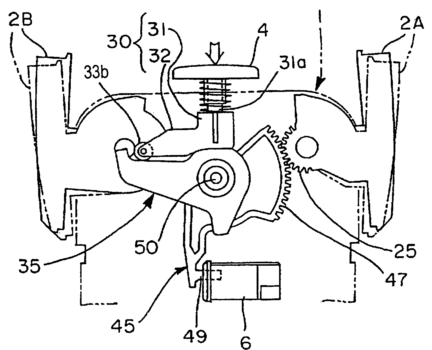
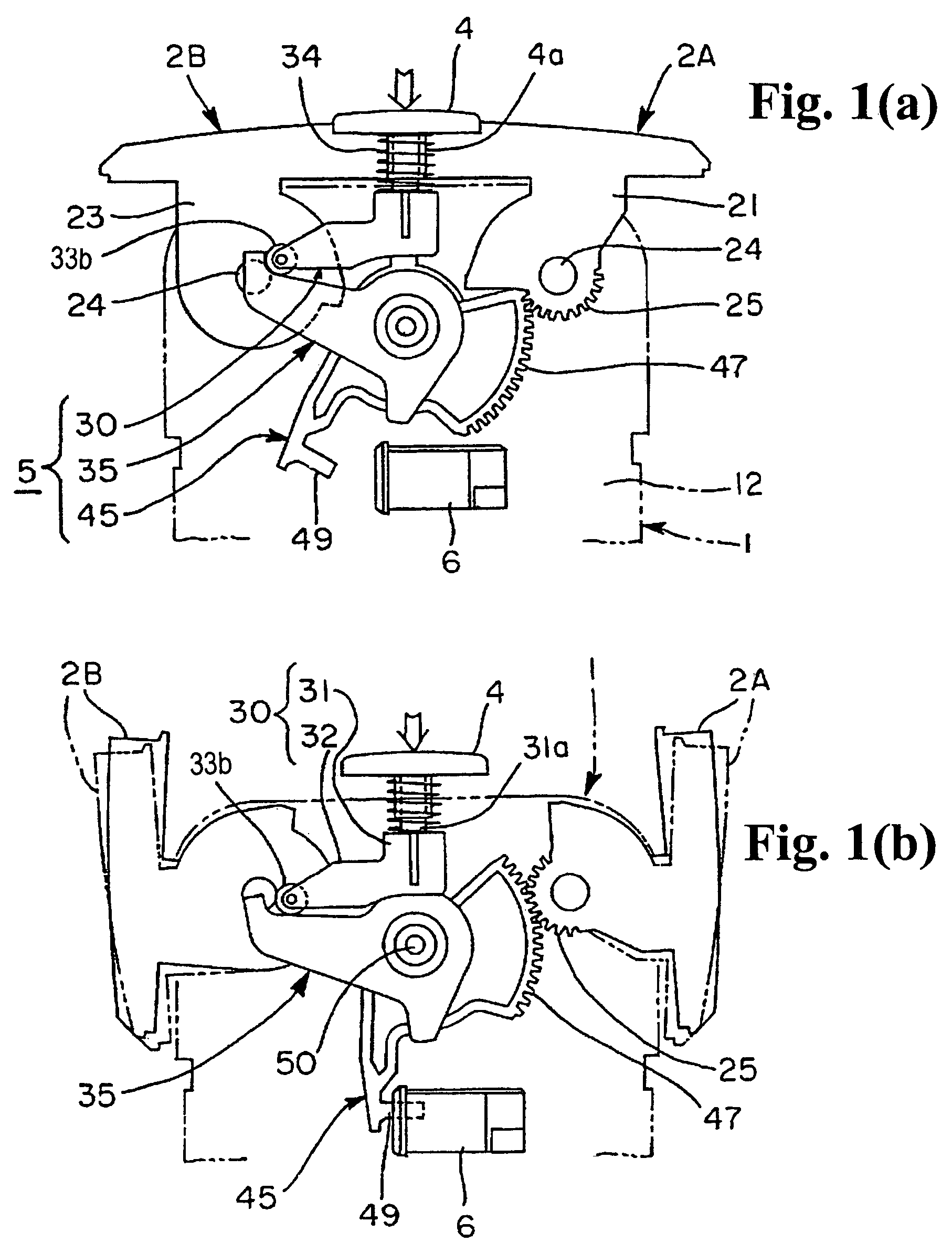
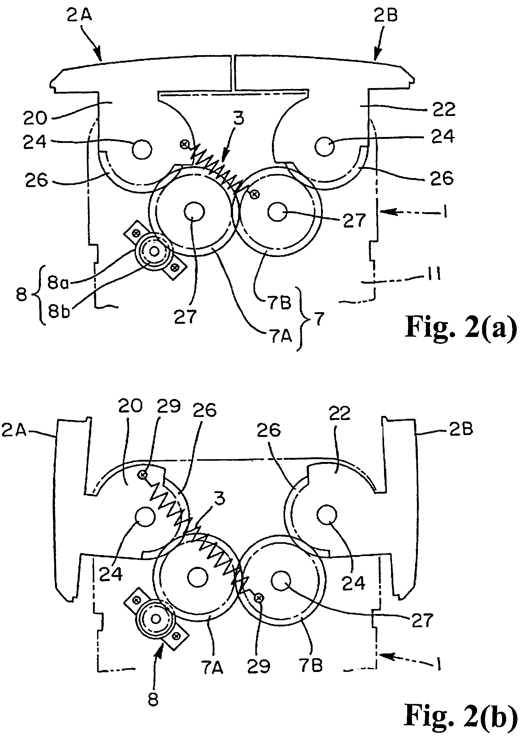
[0048]The cover opening and closing device of the first embodiment shown in FIGS. 1(a) and 1(b) to FIGS. 6(a) and 6(b), just as in Patent Document 1, is made as a mechanism for opening and closing an upper opening of a main body 1 which is housed inside a rectangular box-shaped housing part formed by an automobile console box. The apparatus or mechanism comprises a coil spring 3 as a forcing device, an operation button 4, a switching device 5, a latch 6, a power transmitting device 7, and a damper device 8. The switching device 5 is constituted by a cam 35 which is rocked or rotated by a movable body 30 by a push operation of the button 4, an acceleration gear 45 which is linked to the cam 35 by a force amplifying gear mechanism 40, and a catching claw 49 which is provided on a part of the acceleration gear 45, and the like.

[0049]The main body 1 is partitioned by front and rear walls 11 and 12, a bottom wall 13, and reinforcing pieces or projecting walls 14 provided on both sides of...

modified example 1

[0064]The modified example shown in FIGS. 7(a) and 7(b) and FIGS. 8(a) and 8(b) switches one cover body 2 to rotate between the closed position and the open position using the cover opening and closing device. The structure comprises as constituent members: a coil spring 3 as a forcing device which normally forces the cover body 2 pivotally supported on the main body 1 toward the direction of the closed position; a single push operation button 4 which is provided on the main body 1 or a border member 10 for the main body; a switching device 5 which has a cam 35 placed opposite to the button 4 and an acceleration gear 45 being linked to the cam 35 and engaging a gear part 25 provided on the cover body 2 and a catching claw 49 provided on the acceleration gear 45, and switches the cover body 2 from the closed position to the open position in opposition to the force of the coil spring 3 by the cam 35 and the acceleration gear 45 by the push operation of the button 4; and a latch 6 whic...

modified example 2

[0067]When the latch 6 which catches and releases the catching claw 49 is a push-push catching mechanism, as shown in FIG. 1(b), the cover body moves slightly toward the open direction when the holding of the catching claw 49 is released by the push operation of the button 4. The modified example shown in FIG. 9 to FIGS. 14(a) and 14(b) eliminates such a slight movement of the cover. Structurally, a bracket 9A (corresponding to the bracket 9) has an arm 51 and a trace pin 53 protruding on the free end of the arm 51. Inside the vertical part 31 of the movable body 30, a sliding body 55 in which a cam groove 56 is formed; a frame member 57 which is built into the vertical part 31 in a state of retaining the sliding body 55; a lock member 59 which is built in below inside the frame 57; a coil spring 58a which forces the frame member 57 upwardly; and a coil spring 58b which forces the lock member 59 toward the direction of protruding from the frame member 57 are built in. They are featu...


PUM


Abstract

A cover opening and closing device switches a cover body to rotate between a closed position and an open position. The cover opening and closing device includes a single operation button for switching the cover body between the closed position and the open position, a forcing device for forcing the cover body at least toward the closed position from a near closed position when the cover body is closed, and a switching device for releasing the cover body in the open position and allowing the cover body to rotate toward the closed position when the operation button is pushed.

Description

BACKGROUND OF THE INVENTION AND RELATED ART STATEMENT[0001]The present invention relates to a cover opening and closing device for switching a cover body between an open position and a closed position relative to a corresponding surface (for example, an opening or operating panel of switches, and the like) of a main body.[0002]A cover opening and closing device used on a vehicle console or the like has been disclosed in Japanese Patent Publication (Kokai) No. 2003-129742. A cover body is usually forced toward an open position by a forcing device. A cover body is switched from the open position to a closed position in opposition to the force of the forcing device, and stays at the closed position by holding a catching claw on the cover body to a latch on the main body in the closed position. In a case that the cover body is divided into two parts, an idle gear or the like is interposed between the two parts for synchronously switching each part between the open position and the close...

Claims


Application Information

Patent Timeline
Patent Type & Authority Patents(United States)
IPC IPC(8): E05C3/02B60R7/06B60R7/14E05B17/00E05B65/12E05C7/04E05C17/02E05C19/02E05F11/00E05F11/54E05F17/00H01H13/70
CPCE05B83/30E05C17/02E05F11/00E05F17/004E05B77/42E05B77/06E05C7/04E05C19/022Y10S292/37E05Y2201/21E05Y2201/254E05Y2201/266Y10S292/04E05F11/54Y10T292/1043B60R7/06E05F1/08E05F3/00
Inventor ICHIMARU, TAKAHIDE
Owner NIFCO INC
Why Eureka
Try Eureka