Power supply monitoring device

a monitoring device and power supply technology, applied in power supply testing, process and machine control, instruments, etc., can solve the problems of inability to detect operational malfunctions in monitored circuits, and long time-consuming and laborious monitoring, so as to accurately and quickly detect operational malfunctions

Active Publication Date: 2008-08-05
FUJITSU LTD
View PDF6 Cites 10 Cited by
  • Summary
  • Abstract
  • Description
  • Claims
  • Application Information

AI Technical Summary

Benefits of technology

[0013]It is accordingly an object of the present invention to provide a power supply monitoring device which can accurately and quickly detect an operational malfunction which occurs in a monitored circuit due to an instantaneous interruption of a power supply voltage, a sudden reduction thereof, or the like without stopping services provided by the device for a long time.

Problems solved by technology

Therefore, there has been a problem that an occurrence of an operational malfunction in the monitored circuit can not be instantaneously detected by the reduction of the power supply voltage, and services provided by the device are kept stopped for a long time.
Consequently, there has been a problem that the services provided by the device are stopped even when stopping the services is not necessary.

Method used


Image

  • Power supply monitoring device
  • Power supply monitoring device
  • Power supply monitoring device

Examples


embodiment

[1]: FIGS. 1A, 1B, and 6

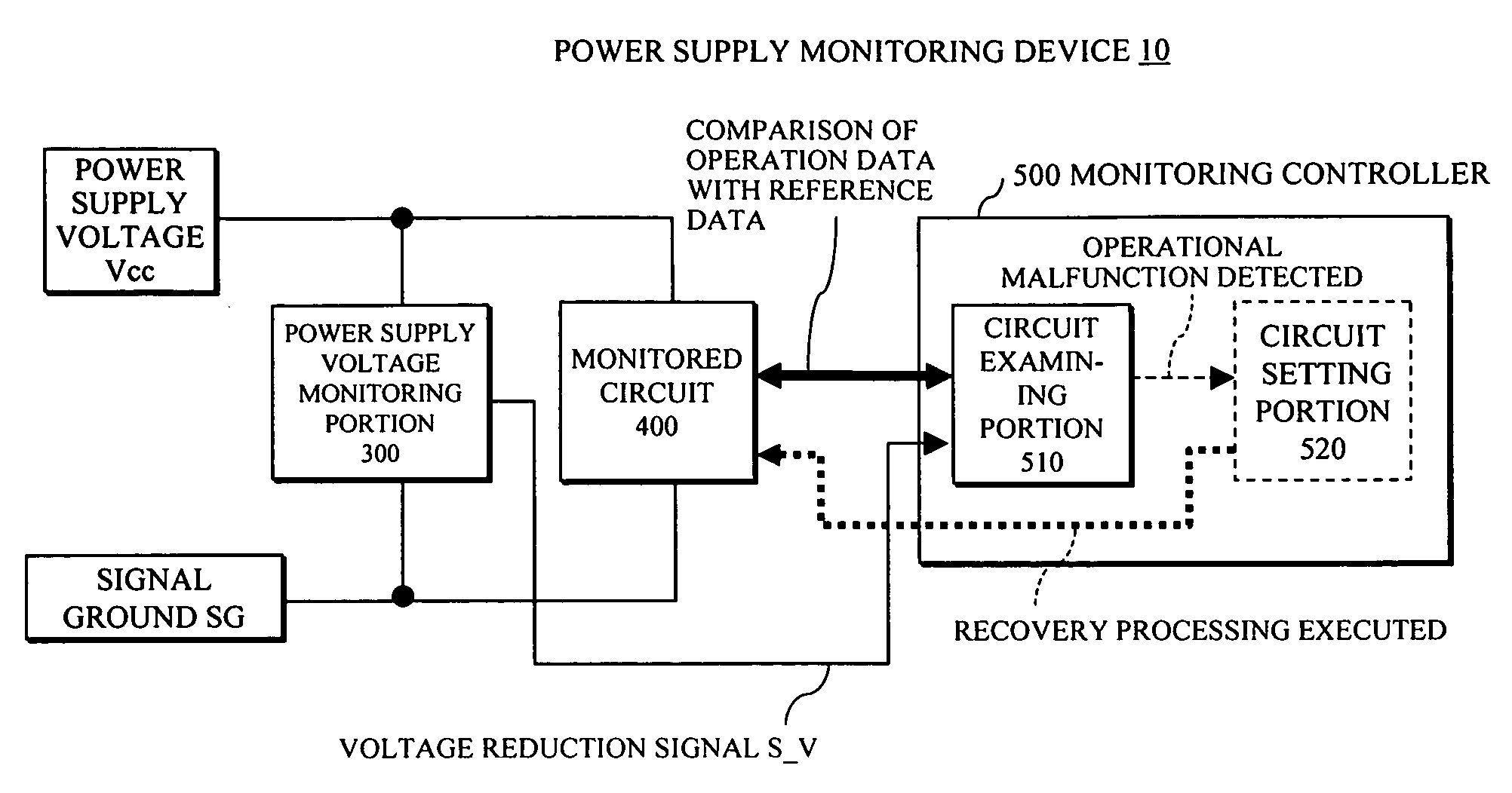
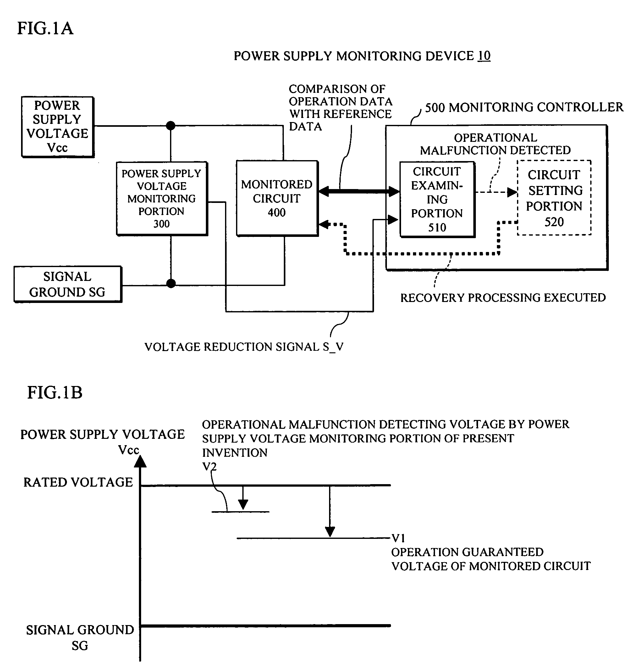
[0068]The power supply monitoring device 10 shown in FIG. 6 is composed of the power supply voltage (unit) Vcc, the power supply voltage monitoring portion 300, the monitored circuit 400, and the monitoring controller 500 including the circuit examining portion 510 and the circuit setting portion 520, in the same way as FIG. 1A.

[0069]Furthermore, in addition to the arrangement shown in FIG. 1A, the monitored circuit 400 is provided with a register RG for writing therein reference data which becomes operation data during operation.

[0070]Also, the circuit examining portion 510 is provided with a comparing portion 511 comparing the operation data of the monitored circuit 400 with the reference data of the circuit examining portion 510 itself, a determining portion 512 determining presence or absence of an operational malfunction of the monitored circuit 400 based on the comparison result of the comparing portion 511. The circuit setting portion 520 is provided w...


PUM


Abstract

In a power supply monitoring device, a power supply voltage monitoring portion always monitors a power supply voltage supplied to a monitored circuit and outputs a voltage reduction signal when detecting that the power supply voltage is reduced below a predetermined threshold (e.g. a second voltage higher than a voltage guaranteeing a normal operation of the monitored circuit and lower than a rated voltage). A monitoring controller having received the voltage reduction signal determines whether or not an operational malfunction has occurred in the monitored circuit by comparing operation data of the monitored circuit with reference data of the monitoring controller itself. Also, the monitoring controller executes recovery processing (reset processing or reference data overwrite processing) suitable for the monitored circuit referring to a prestored recovery processing type specific to the monitored circuit when detecting an operational malfunction of the monitored circuit.

Description

BACKGROUND OF THE INVENTION[0001]1. Field of the Invention[0002]The present invention relates to a power supply (or power source) monitoring device, and in particular to a power supply monitoring device monitoring a power supply voltage supplied to a monitored circuit to protect the monitored circuit from an operational malfunction which occurs due to a reduction of the power supply voltage or the like.[0003]2. Description of the Related Art[0004]As the above-mentioned power supply monitoring device, the following prior art examples [1] and [2] have been known.Prior Art Example [1]: FIGS. 14A and 14B[0005]A power supply monitoring device 10 shown in FIG. 14A is composed of a fuse / electromagnetic wave filter 100 which is connected to a ground GND and is supplied with an input voltage Vin (e.g. “−48 V”) for the whole device, onboard power supplies 200_1-200_3 (hereinafter, occasionally represented by a reference numeral 200) respectively receiving an output voltage Vout from the fuse / ...

Claims


Application Information

Patent Timeline
Patent Type & Authority Patents(United States)
IPC IPC(8): G08B21/00
CPCG01R31/31721G01R31/3004
Inventor SUGAMA, KOICHISHIMIZU, NOBORUCHIKAZAWA, TSUTOMUKAYAMA, RYUJIYAJIMA, KENICHIKATAYANAGI, YUKIOKAIGA, TAKASHI
Owner FUJITSU LTD
Why Eureka
Try Eureka