Magnetic disk slider having improved inclination margins in a rolling direction

a technology of rolling direction and inclination margin, which is applied in the direction of magnetic recording, information storage, maintaining head carrier alignment, etc., can solve the problems of reducing the lifting force, affecting the inclination margin, and damage to the disk

Inactive Publication Date: 2008-08-05
HITACHI GLOBAL STORAGE TECH NETHERLANDS BV
View PDF9 Cites 4 Cited by
  • Summary
  • Abstract
  • Description
  • Claims
  • Application Information

AI Technical Summary

Benefits of technology

[0020]FIG. 4 is a flowchart of the process steps applied in the present invention.
[0021]FIG. 5 is a plan view of a magnetic head slider according to a second embodiment of the present invention.
[0022]FIG. 6 is a plan view of a magnetic head slider according to a third embodiment of the present invention.
[0023]FIG. 7 is a plan view of a magnetic head slider according to a fourth embodiment of the present invention.
[0024]FIG. 8 is a plan view of a magnetic head slider according to a fifth embodiment of the present invention.
[0025]FIG. 9 is a plan view of a magnetic head slider according to a sixth embodiment of the present invention.

Problems solved by technology

The local deformation causes fluctuations in flying characteristics, impedes low flying and stable flying, and results in disk damage due to contact during load / unload states.
The problem of the insufficiency in the lifting force based on air-bearing characteristics does not occur in conventional 3.5-inch magnetic disk drives or in the high-speed types of 2.5-inch magnetic disk drives operating at magnetic disk speeds such as 5400 rpm or 7200 rpm.
The problem of a decrease in the lifting force is a new problem that is produced by practical use of magnetic disk drives that use a small disk such as 25.4 mm (1″) or 45.7 mm (1.8″).
A decrease in the lifting force causes several problems.
A first problem is that air-bearing rigidity decreases and thus that the flying characteristics of the slider deteriorate.
A second problem is that since the suspension load needs to be reduced, the shock resistance of the drive during operation decreases.
A third problem is that the sliders operating at both positive and negative pressures have a stabilization region in which negative pressures occur in a negative-pressure area, and a “Bi-Stable” region allowing the slider to take both a high-flying mode in which it generates positive pressures even in the negative-pressure area and flies with a flying height of at least 1 μm, and a low-flying mode in which the slider flies with its intended flying height.
A fourth problem is that when the suspension load applied is too small and the slider is too short, if the above-mentioned decrease in flying height is caused by an external disturbance, vibration, or a decrease in atmospheric pressure or if, at a leading edge, the slider comes into contact with the disk during slider loading (hereinafter, the contact is referred to as pitch-down), the slider maintains its attitude and continue to be in contact because the slider is unable to escape from that state.
Consequent damage to the contact section of the disk will result in information being lost.
In a worst case scenario, a crash may even occur.
A fifth problem is that because a decrease in bearing area reduces the lifting force and the negative pressure at the same time, the decrease rate of flying height with respect to a decrease in atmospheric pressure is increased, which results in flying height margins being lost.

Method used


Image

  • Magnetic disk slider having improved inclination margins in a rolling direction
  • Magnetic disk slider having improved inclination margins in a rolling direction
  • Magnetic disk slider having improved inclination margins in a rolling direction

Examples


Embodiment Construction

[0029]Preferred embodiments of the present invention will be described in detail below referring to FIGS. 1 to 12. While technically preferable limitations are imposed in various forms on the embodiments described hereunder, the scope of the invention is not limited to these embodiments.

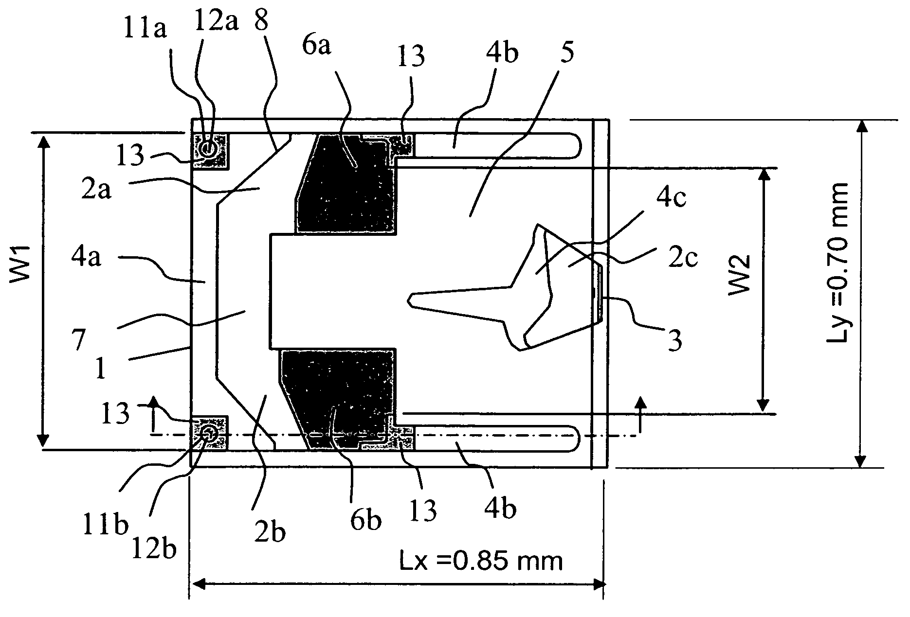
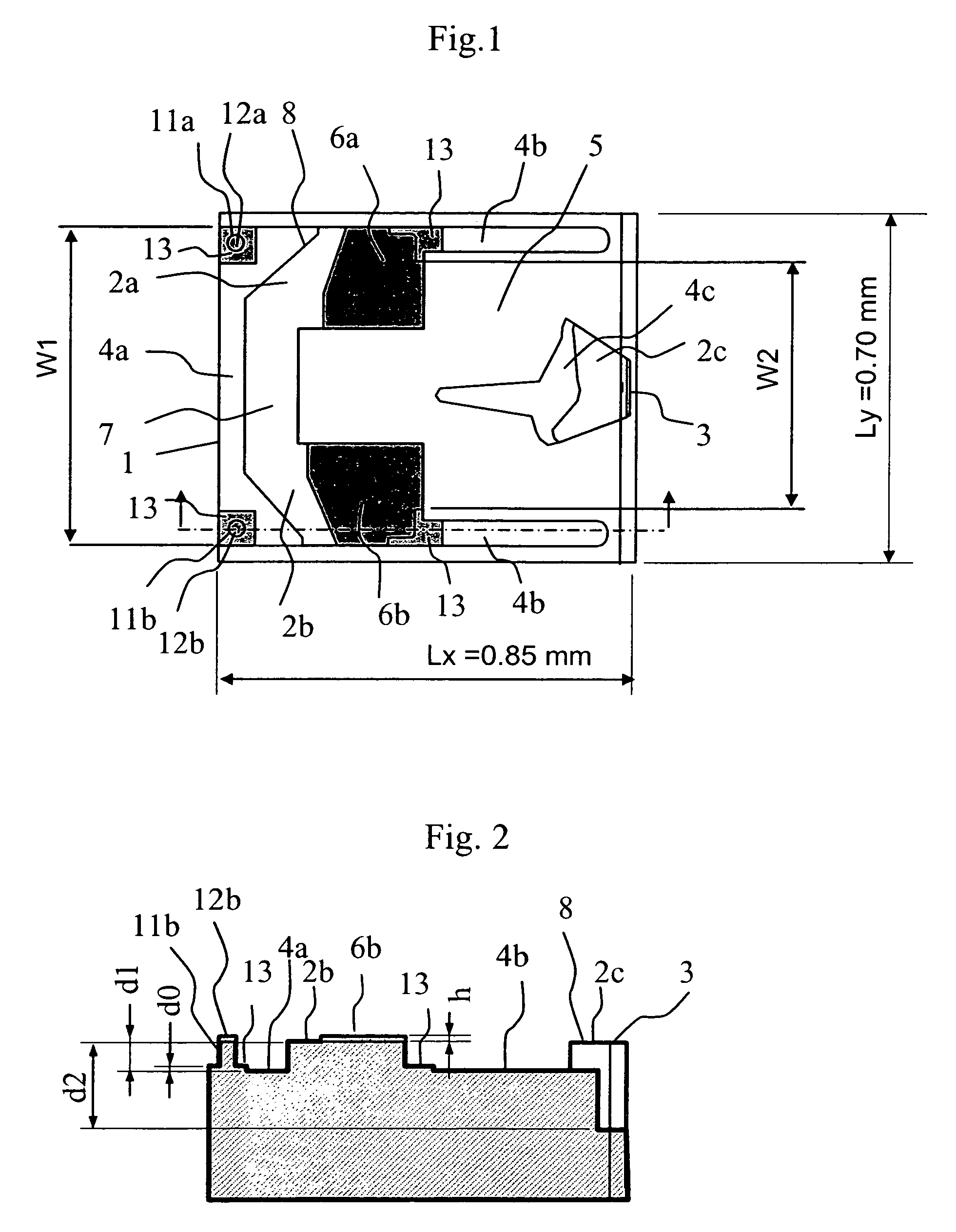
[0030]FIG. 1 is a plan view of a magnetic head slider according to a first embodiment, and FIG. 2 is a sectional view thereof. As shown in FIGS. 1 and 2, in order to generate a lifting force by applying effects of an air bearing, the magnetic head slider according to the present embodiment has a leading-side shallow-grooved surface 4a on the leading side of a bearing surface 8 of a slider 1, and one pair of leading-side flying surfaces 2a and 2b adjacent to the shallow-grooved surface 4a, at rear thereof. The leading-side flying surfaces 2a, 2b are connected at respective leading-side edges to a connection flying surface 7 to form one flying surface. Side shallow-grooved surfaces 4b extending close t...


PUM

PropertyMeasurementUnit
heightaaaaaaaaaa
diameteraaaaaaaaaa
diameteraaaaaaaaaa

Abstract

A magnetic head slider suitable for a disk drive measuring 1.8 inches or less in disk size incorporates preventive measures against the decreases in lifting force that occur in small sliders with a slider width of 0.8 mm or less. The present invention improves the inclination margins of the flying slider in a rolling direction at the lowest flying point, and achieves low flying height and stable flying. The slider is constructed with stepped surfaces on the slider's leading-side flying surface formed up of shallow-grooved surfaces and a deep-grooved surface so that a trailing-side width W2 between the stepped surfaces is smaller than a leading-side width W1.

Description

BACKGROUND OF THE INVENTION[0001]The present invention relates to magnetic head sliders that, in magnetic disk drives and the like, travel along the surfaces of recording media with a very small flying clearance or come into intermittent contact with the recording medium surfaces. More particularly, the invention is concerned with magnetic head sliders that are not only excellent in shock resistance and in flying characteristics in a disk drive that uses small-diameter disks of 1.8 inches or less, but also suitable for mass production.[0002]Magnetic head sliders are each supported by the flexure installed on a suspension, and fly along the surfaces of magnetic disks with a very small clearance or come into intermittent contact with the magnetic disk surfaces. Data is written and read in this way. A prior art slider 101 is illustrated in FIGS. 11 and 12. The slider 101 has a medium-facing surface (bearing surface) 108, which is constructed of a flying surface 102 (102a, 102b, 102c), ...

Claims


Application Information

Patent Timeline
Patent Type & Authority Patents(United States)
IPC IPC(8): G11B5/60
CPCG11B5/6005
Inventor AGARI, HIROSHIDORIUS, LEE KEVINHASHIMOTO, KIYOSHITAKEUCHI, YOSHINORI
Owner HITACHI GLOBAL STORAGE TECH NETHERLANDS BV
Why Eureka
Try Eureka