Weighing system having an angle lever with a long vertical lever arm

a technology of vertical lever and weighing system, which is applied in the direction of weighing apparatus using counterbalance, weighing apparatus details, instruments, etc., can solve problems such as unoptimized, and achieve the effect of large transmission ratio

Active Publication Date: 2008-08-12
SARTORIUS LAB INSTR GMBH & CO KG
View PDF8 Cites 0 Cited by
  • Summary
  • Abstract
  • Description
  • Claims
  • Application Information

AI Technical Summary

Benefits of technology

[0006]The heretofore conventional side-by-side arrangement of the angle levers and the permanent magnet system in the area between the connecting rods is thus abandoned. Instead, the permanent magnet system and the long lever arm with the coil are relocated to the area below the connecting rods. In combination with short connecting rods, this results in a weighing system with a small base. Despite the small horizontal dimensions of the weighing system, the length of the long lever arm is not limited in practice, since a longer long lever arm increases only the overall height. As a result, a large transmission ratio can be realized even with a single lever.

Problems solved by technology

Both of the above weighing systems require a relatively large base area, however, so that they are not optimal for applications where several weighing system are to be spaced close together side-by-side.

Method used


Image

  • Weighing system having an angle lever with a long vertical lever arm
  • Weighing system having an angle lever with a long vertical lever arm
  • Weighing system having an angle lever with a long vertical lever arm

Examples


Embodiment Construction

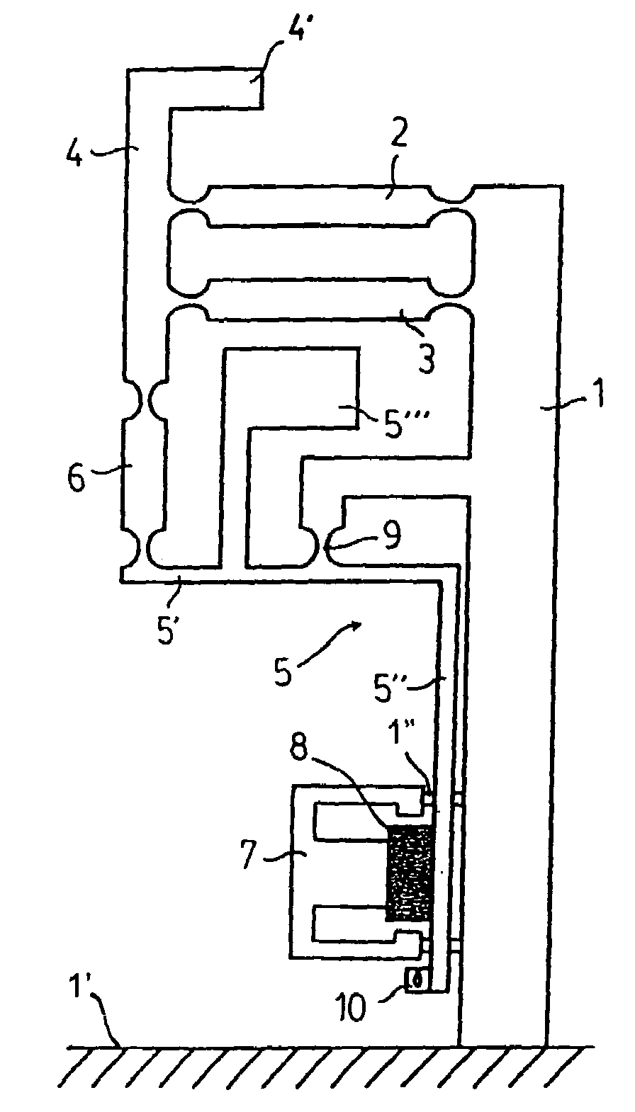
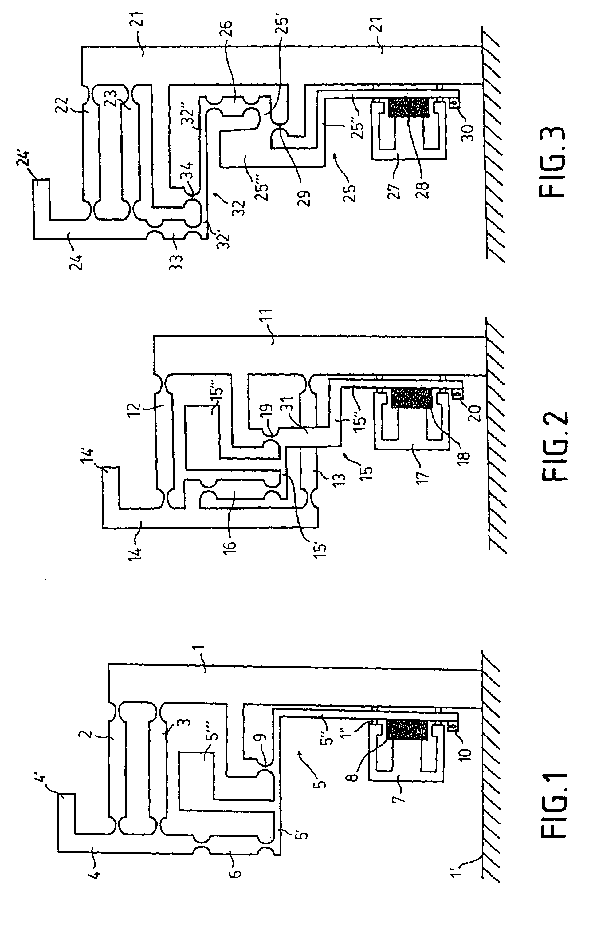
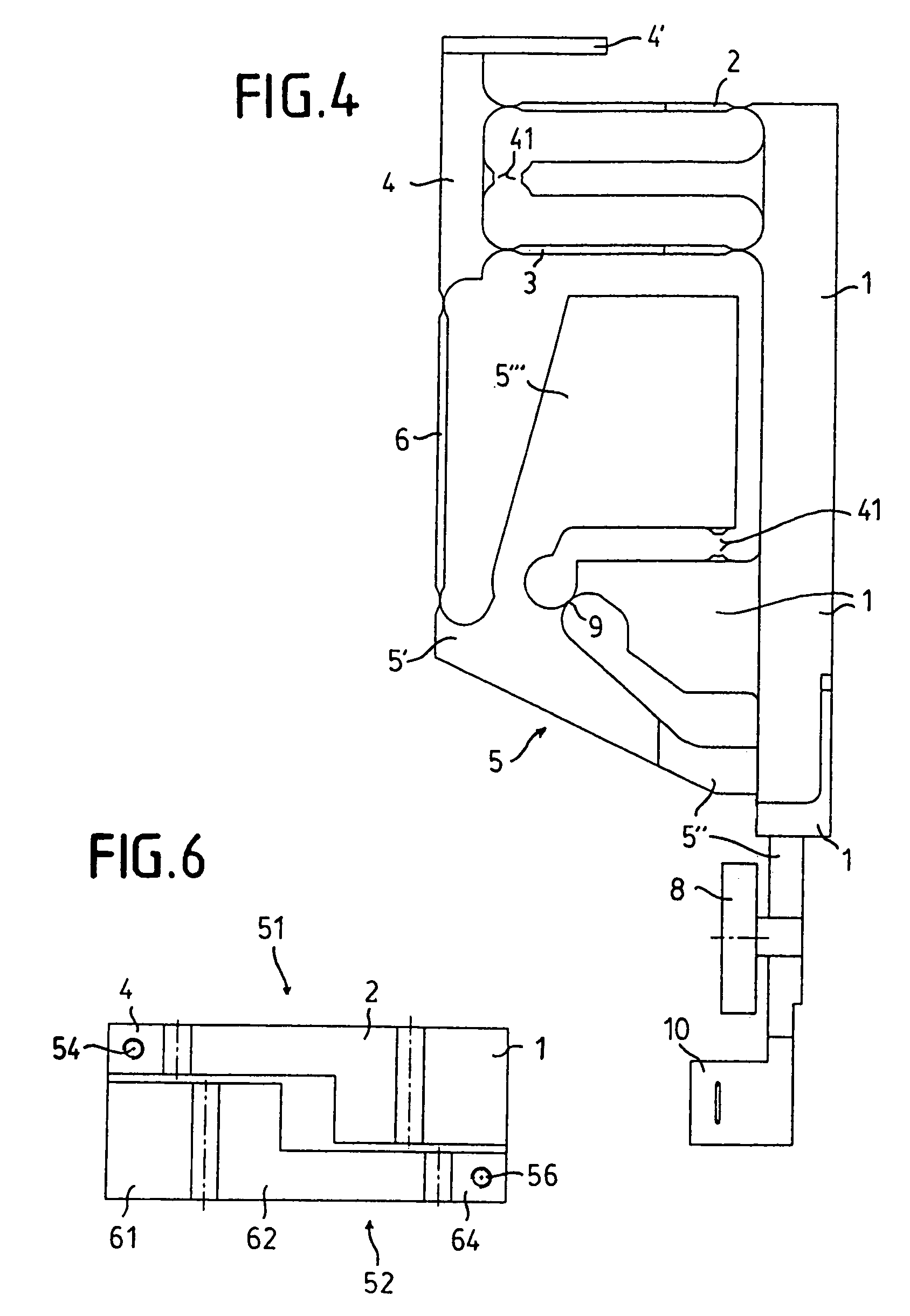
[0017]The weighing system, which in FIG. 1 is shown only schematically in a side view, has a base 1 extending from a surface 1′, two connecting rods 2 and 3, a load receiver 4, an angle lever 5, a coupling member 6 for transmitting the weight force to the short lever arm 5′ of the angle lever, a permanent magnet system 7, and a coil 8 which is fixed to the long lever arm 5″ of the angle lever and which is located in the air gap of the permanent magnet system 7. The angle lever 5 is supported on the base 1 so as to be pivotable at a thin spot 9 in the material. Corresponding thin spots in the material indicate the linkage points on the connecting rods 2 and 3 and the coupling member 6. The combined center of gravity of the angle lever 5 and the coil 8 is shifted by means of a top weight 5′″ such that it lies at least approximately at the level of the fulcrum (thin spot 9 in the material). The permanent magnet system 7 is coupled to the base 1 by means of supports 1″. FIG. 1 further s...


PUM


Abstract

A weighing system that operates according to the principle of electromagnetic force compensation, having two connecting rods (2, 3) which are fashioned as a parallel guide and connect a load receiver (4) to a base area (1) fixed to the housing, and having an angle lever (5) mounted on the base area. The force due to weight that is transmitted by the load receiver acts upon the short lever arm (5′) of the angle lever via a coupling element, and a coil projecting into the air gap of a permanent magnet system (7) is fastened to the long lever arm (5″). The weighing system occupies only a small area since the long lever arm takes the form of a vertical lever arm and extends, at least in part, in the area underneath the connecting rods of the parallel guide. The permanent magnet system is likewise arranged underneath the connecting rods of the parallel guide.

Description

[0001]This is a Continuation of International Application PCT / EP2005 / 007662, with an international filing date of Jul. 14, 2005, which was published under PCT Article 21(2) in German, and the disclosure of which is incorporated by reference into this application in its entirety.FIELD AND BACKGROUND OF THE INVENTION[0002]The invention relates to a weighing system operating according to the principle of electromagnetic force compensation, having two connecting rods which, in the form of a parallel guide, connect a load receiver to a base fixed to the housing, and having an angle lever mounted to the base area. The weight force transmitted by the load receiver acts on the short lever arm of the angle lever, and a coil projecting into the air gap of a permanent magnet system is fixed to the long lever arm of the angle lever.[0003]A weighing system of this type is disclosed, for example, in German publication DE 31 27 939 C2. German publication DE 195 40 782 C1 also describes such a weig...

Claims


Application Information

Patent Timeline
Patent Type & Authority Patents(United States)
IPC IPC(8): G01G7/04G01G7/02G01G21/24
CPCG01G21/244G01G7/02
Inventor WALTER, FABIANKUHLMANN, OTTOFLEISCHER, PETERLANGNER, WILFRIED
Owner SARTORIUS LAB INSTR GMBH & CO KG
Why Eureka
Try Eureka