Magnetic transmission speed-transformation device

A technology of speed change and magnetic transmission, applied in electromechanical transmissions, electromechanical devices, electric components, etc., can solve the problems of limited application, transmission power of magnetic gears and small transmission ratio.

Inactive Publication Date: 2012-11-14
DALIAN JIAOTONG UNIVERSITY
View PDF5 Cites 15 Cited by
  • Summary
  • Abstract
  • Description
  • Claims
  • Application Information

AI Technical Summary

Problems solved by technology

[0003] Although the magnetic gear has the above-mentioned outstanding advantages, due to the limitations of the magnetic material and its own transmission str

Method used


Image

  • Magnetic transmission speed-transformation device
  • Magnetic transmission speed-transformation device
  • Magnetic transmission speed-transformation device

Examples


Embodiment Construction

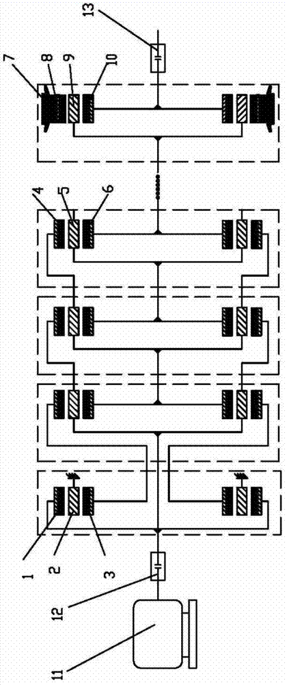
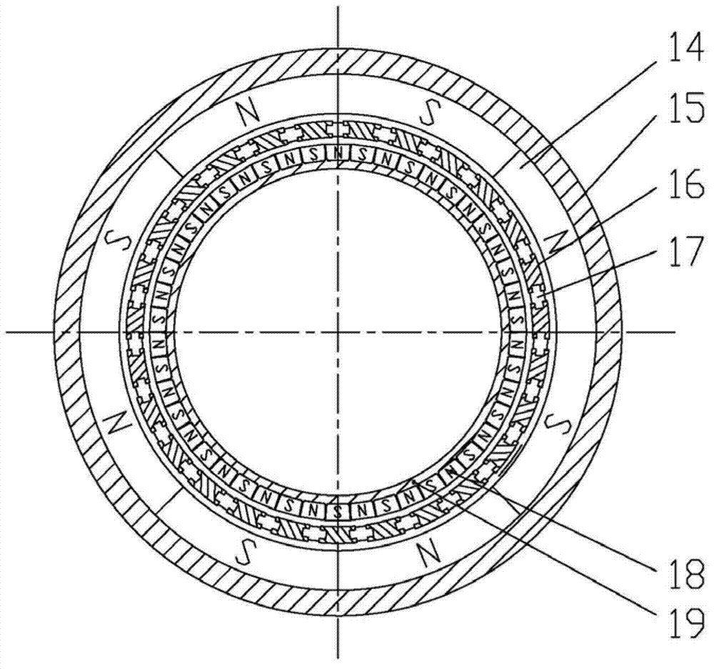
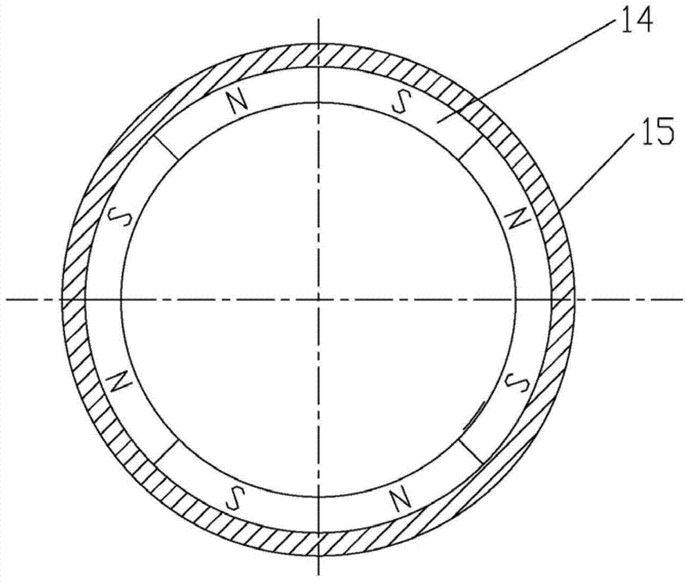
[0069] The present invention will be further described below in conjunction with the accompanying drawings. Such as Figure 1-14 As shown, a magnetic transmission speed change device is mainly composed of an input module, a connection module and an output module. The magnetic flux circuit of the input module is composed of three layers of components and two layers of air gaps: the three layers of components are the outer magnetic coil component A1, the magnetic ring component A2 and the inner magnetic coil component A3. The outer magnetic ring assembly A1 is composed of a plurality of tile-shaped permanent magnets A14 with opposite magnetic poles and an annular yoke A15; the magnetic adjustment ring assembly A2 is composed of a plurality of pure iron or magnetic steel sheets 16 through a non-magnetic material 17 in a fence structure; The magnetic coil assembly A3 is also composed of a plurality of tile-shaped permanent magnets B18 with opposite magnetic poles and an annular y...


PUM


Abstract

The invention discloses a magnetic transmission speed-transformation device, which comprises an input module, connecting modules and an output module; the input module is connected with the connecting modules through double-layer couplers; the connecting modules is connected with the output module through the double-layer couplers; cascading number of the connecting modules is one or more than one; and when the cascading number of the connecting modules is more than one, the connecting modules are connected in series through double-layer couplers. According to the invention, the input module is connected with a power input source through an input coupler; power P is output through the input module, the connecting modules and the output module after being input through an input end of the power input source; N connecting modules can be in series according to the load situation to realize shunting transmission of N magnetic speed-transformation mechanisms, and power borne by each magnetic speed-transformation mechanism at P/N; and an output end synthesizes power of the N speed-transformation mechanisms to total power P through an output coupler for output. According to the invention, the quantity of the cascading modules is reasonably changed, so as to change systematic transmission ratio.

Description

technical field [0001] The invention relates to a speed change device in an electromechanical transmission system, in particular to a magnetic drive speed change device. Background technique [0002] The speed change device in the electromechanical transmission system is an indispensable part in the fields of industrial production, transportation, medical care, new energy utilization, etc. The existing speed change device generally adopts rigid contact motion or power represented by mechanical gears. Transmission method, the advantages of this method are small size, high transmission precision, and high reliability when used within a reasonable range of working conditions; the disadvantage is that friction loss, vibration and noise are easily generated during work, and regular lubrication and maintenance are required. . In addition, when the load at the input end changes irregularly, the gears in the mechanical gearbox are easily damaged due to eccentric load operation. Th...

Claims


Application Information

Patent Timeline
IPC IPC(8): H02K51/00
Inventor 葛研军聂重阳杨均悦汤武初邵万珍张文跃辛强
Owner DALIAN JIAOTONG UNIVERSITY
Why Eureka
Try Eureka