Image sensing apparatus, control method therefor, program, and storage medium

a technology of image sensing apparatus and control method, applied in the field of autofocusing technique, can solve the problems of increasing magnification and the number of pixels, unable to increase the autofocusing speed in normal photographing operation, and unable to realize high af precision and high speed of such electronic cameras, so as to achieve the effect of increasing the precision and speed of autofocusing operation

Inactive Publication Date: 2008-08-12
CANON KK
View PDF11 Cites 3 Cited by
  • Summary
  • Abstract
  • Description
  • Claims
  • Application Information

AI Technical Summary

Benefits of technology

[0013]The present invention has been made to overcome the conventional drawbacks, and has as its object to increase the precision and speed of autofocusing operation.

Problems solved by technology

However, it becomes difficult for such an electronic camera to realize both a high AF precision and high speed along with increases in magnification and the number of pixels.
However, in Japanese Patent Laid-Open No. 5-119250, autofocusing operation is done by the autofocusing means using contrast detection in normal photographing operation, and thus the autofocusing speed cannot be increased in normal photographing operation.
When the autofocusing means is switched to one using infrared detection in only a photographing environment in which it becomes difficult to execute autofocusing operation by the autofocusing apparatus using contrast detection, a satisfactory precision of autofocusing operation cannot be obtained.
This technique also suffers the same problems as those of Japanese Patent Laid-Open No. 5-119250.
However, this reference does not provide any solution to noncoincidence between the detection regions of the distance measurement means and focus detection means that is caused b parallax, and any solution to unbalance between the detection precisions of the distance measurement means and focus detection means.

Method used


Image

  • Image sensing apparatus, control method therefor, program, and storage medium
  • Image sensing apparatus, control method therefor, program, and storage medium
  • Image sensing apparatus, control method therefor, program, and storage medium

Examples


first embodiment

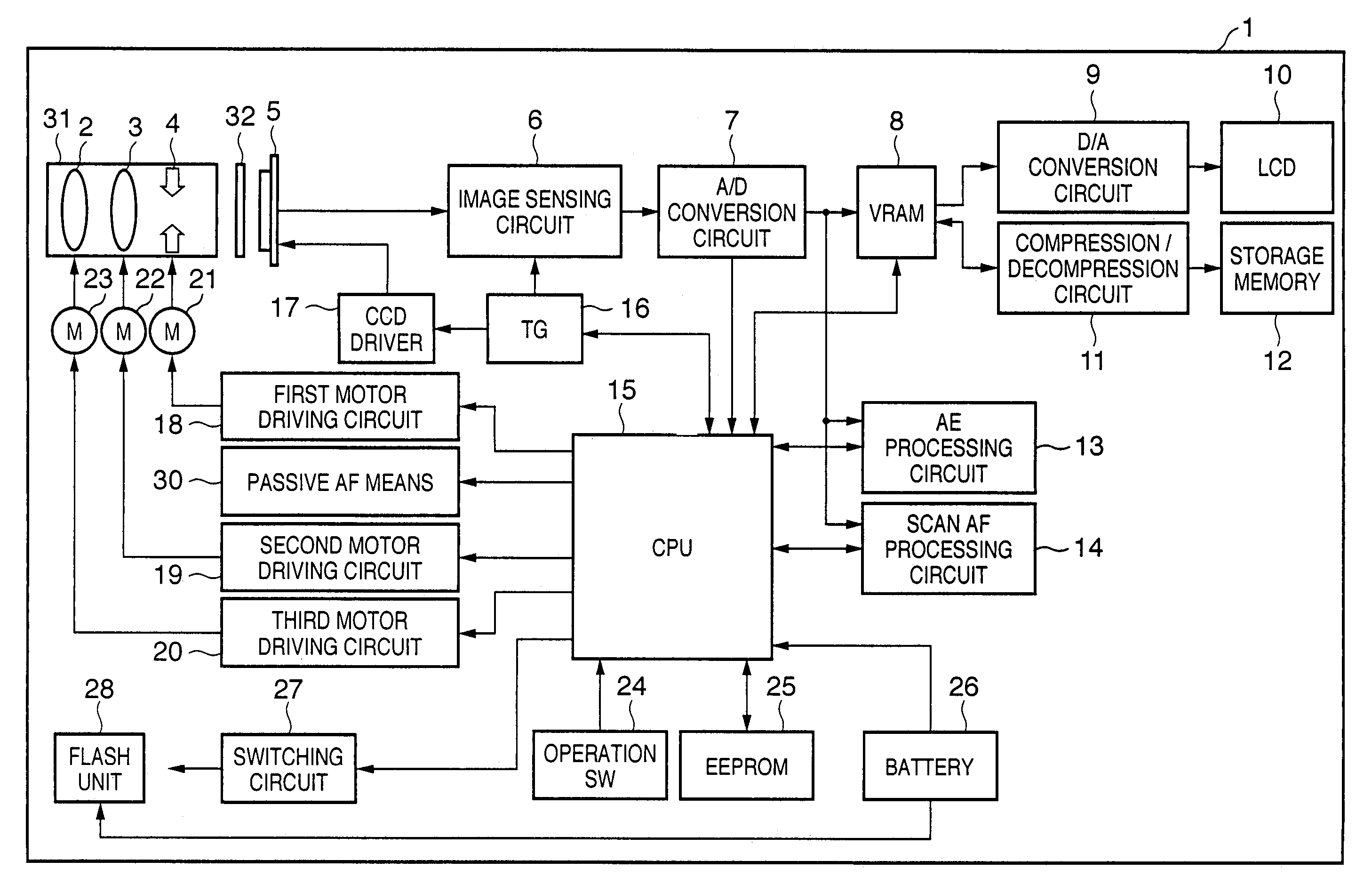
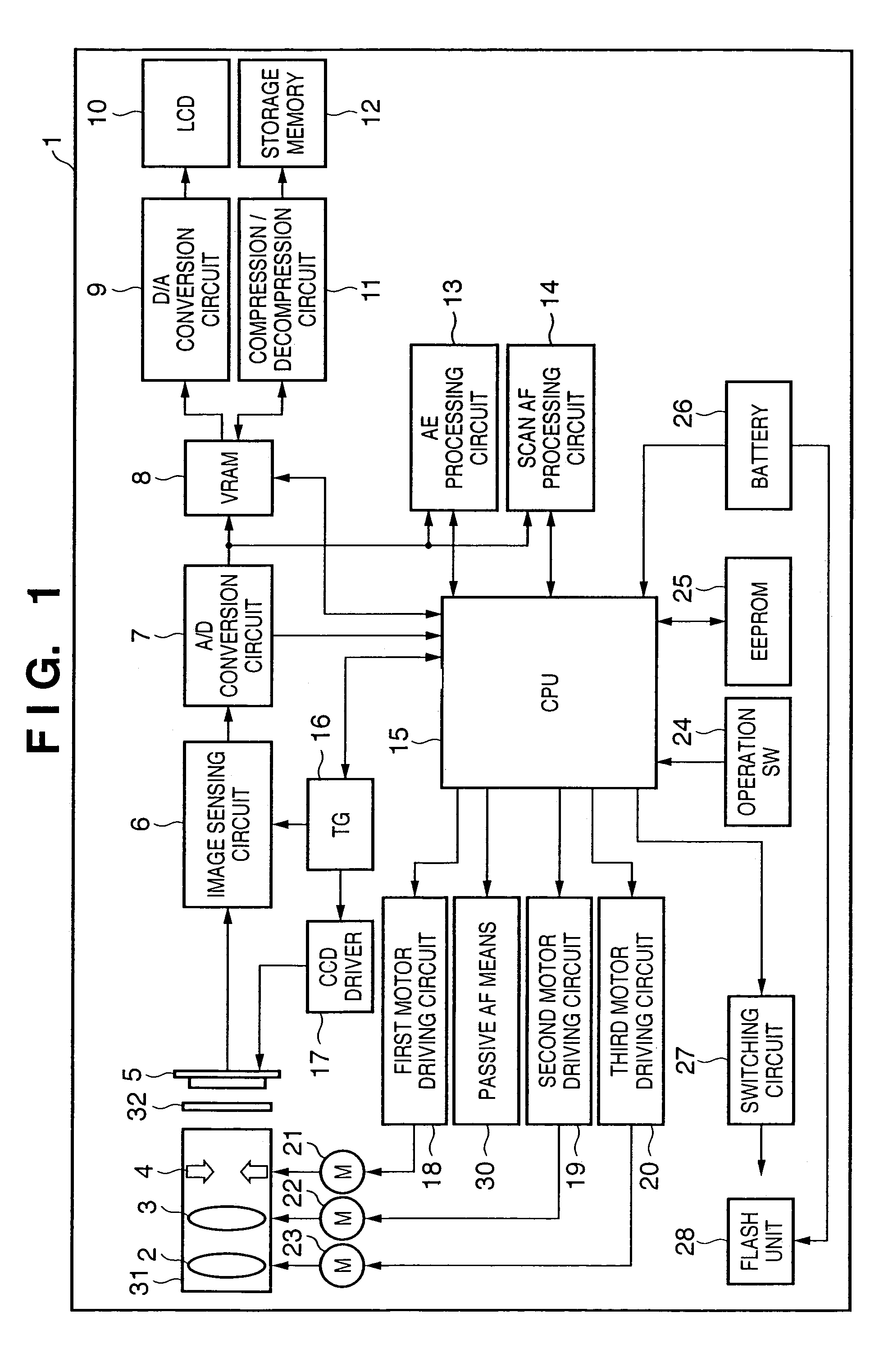
[0038]FIG. 1 is a block diagram showing the configuration of an image sensing apparatus according to the first embodiment of the present invention.

[0039]In FIG. 1, reference numeral 1 denotes an image sensing apparatus; 2, a zoom lens group; 3, a focus lens group; 4, a stop serving as an exposure device and also a light quantity adjustment device which controls the quantity of a beam having passed through a photographing optical system formed from the zoom lens group 2, focus lens group 3, and the like; 31, a photographing lens barrel which incorporates the zoom lens group 2, focus lens group 3, stop 4, and the like; and 5, a solid-state image sensing element (to be referred to as a CCD hereinafter) such as a CCD which forms an object image having passed through the photographing optical system and photoelectrically converts the object image.

[0040]Reference numeral 6 denotes an image sensing circuit which receives an electrical signal photoelectrically converted by the CCD 5 and per...

second embodiment

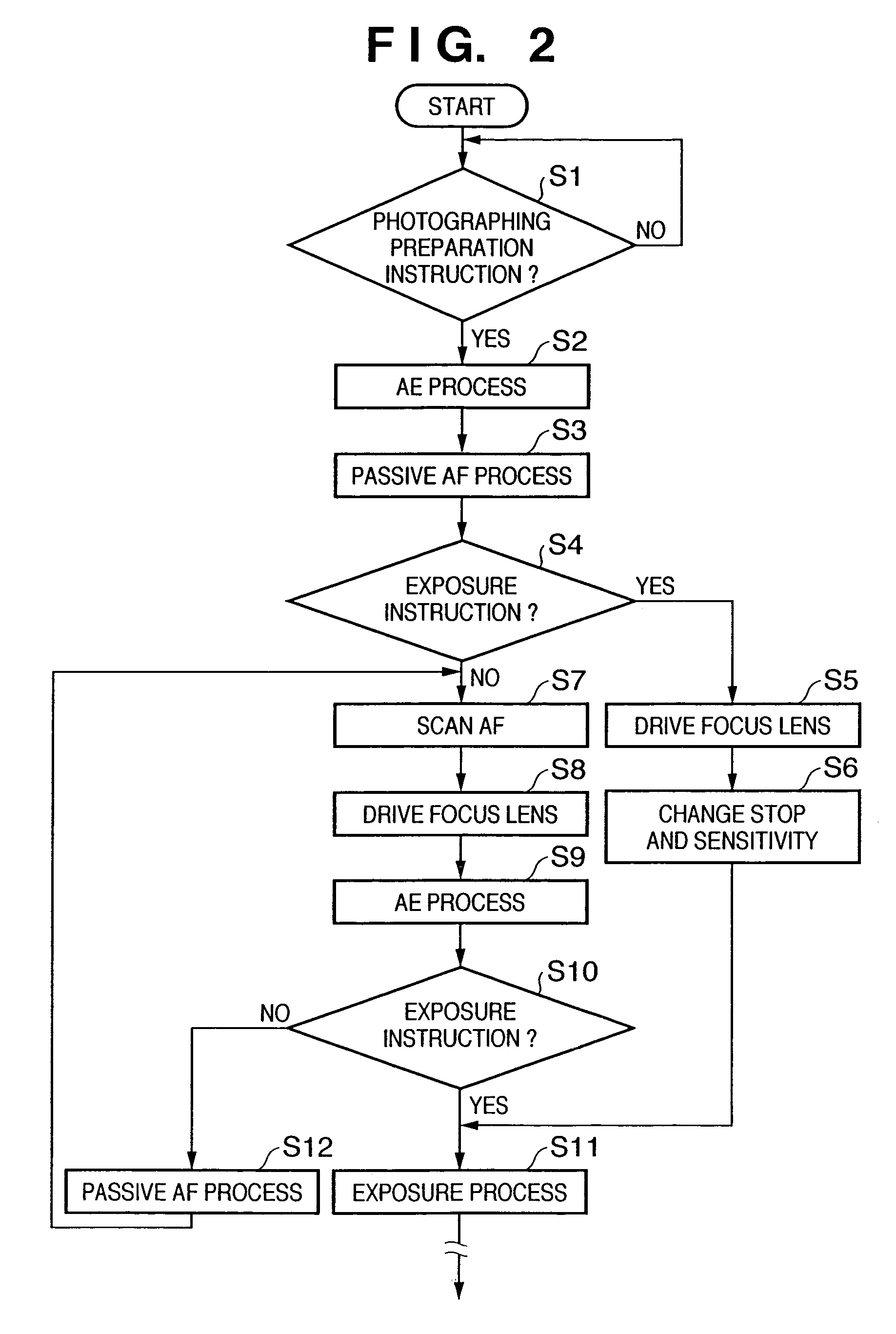
[0118]The basic configuration and basic operation sequence of the second embodiment are the same as those of the first embodiment. FIG. 1 is a block diagram showing an image sensing apparatus according to the second embodiment, and FIG. 2 shows the operation sequence.

[0119]The second embodiment is different from the first embodiment in that the distance measurement result of a passive AF device is corrected using a temperature measured by a thermometer also when the distance measurement result is to be corrected using the result of immediately preceding scan AF. The second embodiment can achieve more accurate correction.

[0120]A process of correcting a distance measurement result by using the result of immediately preceding scan AF will be explained.

[0121]This process is performed when variations in temperature do not occur (can be ignored) in immediately preceding scan AF and current passive AF. The result of passive AF is corrected using information on the in-focus position by scan...

third embodiment

[0126]The third embodiment inhibits correction when no correction precision can be ensured in correcting the result of passive AF by the result of immediately preceding scan AF.

[0127]The basic block configuration of an image sensing apparatus according to the third embodiment is the same as that according to the first embodiment shown in FIG. 1.

[0128]The operation of the image sensing apparatus according to the third embodiment will be explained with reference to the flowchart shown in FIG. 7.

[0129]A photographing process sequence is executed when the main power switch of an image sensing apparatus 1 is ON and the operation mode of the image sensing apparatus is the photographing (recording) mode.

[0130]A CPU 15 displays as an image on an LCD 10 an image which has passed through a photographing lens barrel 31 and is formed on a CCD 5.

[0131]In step S101, zooming operation is done. Whether the zoom switch of an operation switch 24 has been operated is determined. If the zoom switch has...


PUM


Abstract

An object of this invention is to increase the precision and speed of autofocusing operation. To achieve this object, an image sensing apparatus includes a photographing optical system which forms an object image, the photographing optical system having a focusing optical system which adjusts the imaging position of the object image, an image sensing element which photoelectrically converts the object image formed by the photographing optical system to generate an electrical image signal, an in-focus position detection device which detects the in-focus position of the focusing optical system for forming the object image on the image sensing element, on the basis of the image signal generated by the image sensing element while the focusing optical system adjusts the imaging position of the object image, and a distance measurement device which has a plurality of light-receiving portions for receiving a beam from an object, and measures a distance to the object on the basis of output signals from the light-receiving portions.

Description

FIELD OF THE INVENTION[0001]The present invention relates to an autofocusing technique and, more particularly, to an autofocusing technique of adjusting the focus by using an image signal acquired by an image sensing element which photoelectrically converts an object image formed by an image sensing optical system.BACKGROUND OF THE INVENTION[0002]An electronic camera often adopts a low-cost, high-precision contrast detection (scan AF) autofocusing apparatus which adjusts the focus in accordance with the high-frequency component of the image signal of an object image formed on an image sensing element while driving a focus lens. However, it becomes difficult for such an electronic camera to realize both a high AF precision and high speed along with increases in magnification and the number of pixels. To meet this demand, there has been proposed a system which comprises an external distance measurement device of a passive type or the like and measures the distance by switching between...

Claims


Application Information

Patent Timeline
Patent Type & Authority Patents(United States)
IPC IPC(8): G03B13/00H04N5/232G02B7/28G03B13/36G02B7/30G02B7/36H04N101/00
CPCH04N5/23212H04N23/673
Inventor KONISHI, KAZUKITERAYAMA, KOTA
Owner CANON KK
Why Eureka
Try Eureka