Method of generating an interpolation image, an interpolation image generating apparatus, and an image display system using the same
a technology of interpolation image and generating apparatus, applied in the field of generating interpolation image, an interpolation image generating apparatus, and an image display system using the same, can solve problems such as picture degradation (deterioration), and blurring phenomenon to produ
- Summary
- Abstract
- Description
- Claims
- Application Information
AI Technical Summary
Benefits of technology
Problems solved by technology
Method used
Image
Examples
first embodiment
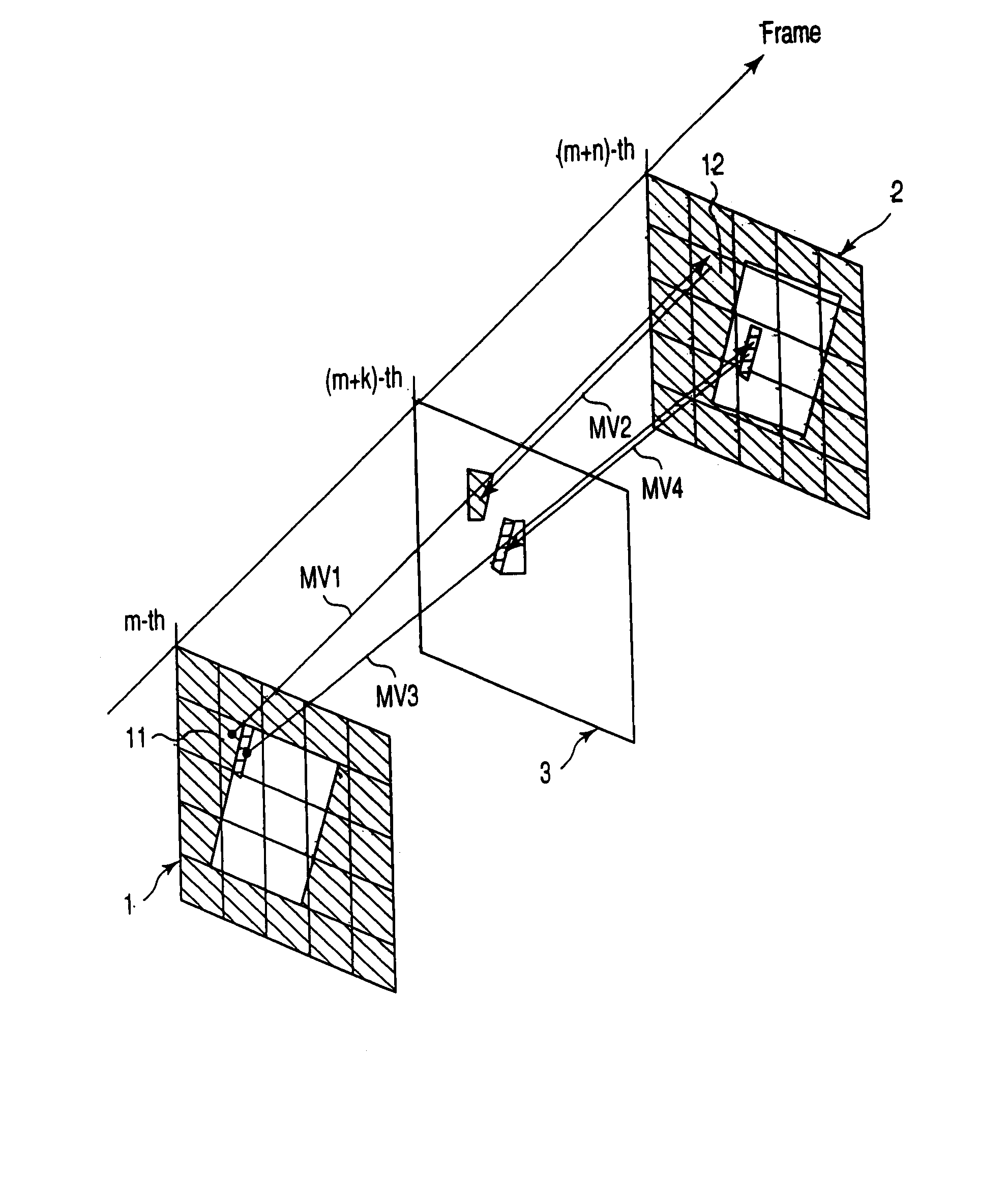
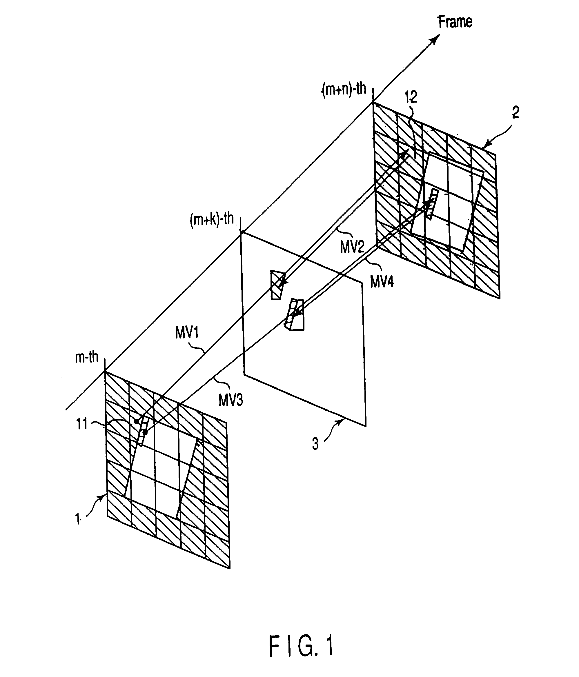
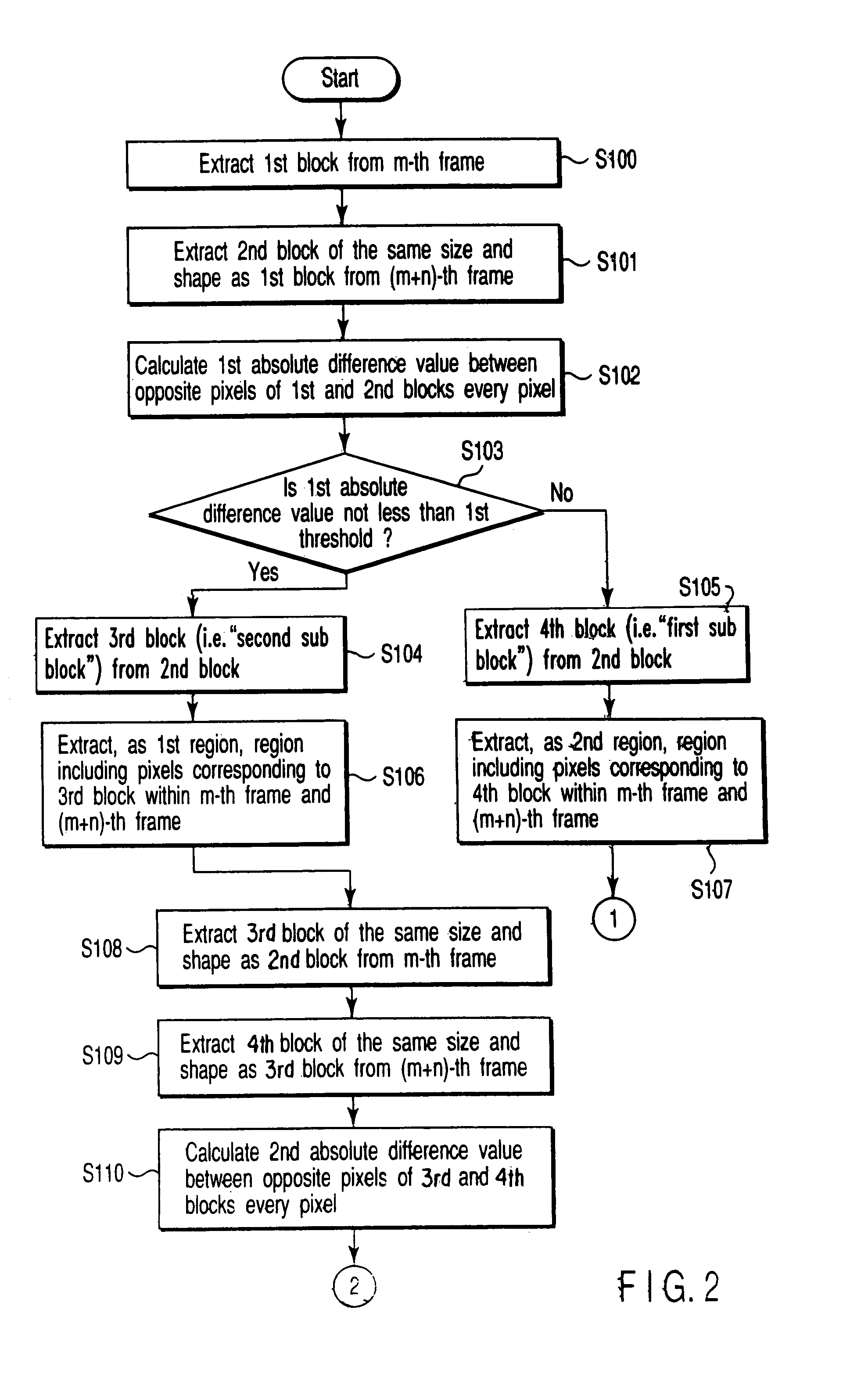
[0036]As shown in FIG. 1, an interpolative image is generated in a time position of a (m+k)-th frame 3 ((k is a real number between 0 and n)) between an m-th frame 1 (m is an integer) and a (m+n)-th frame 2 (n is an integer other than 0) of an original image comprising of a plurality of pixels. The first embodiment of the present invention uses a procedure shown in flow charts of FIGS. 2 and 3. M=1 and n=1, namely the m-th frame and the (m+n)-th frame are described as two consecutive frames of a video. k assumes 0.5, for example.
[0037]At first, as shown in FIG. 4, image data of the m-th frame 1 is divided into a plurality of first blocks 11 to extract sequentially the first blocks 11 (step S100). A second block of the same size and shape as each of the first blocks 11 is extracted from image data of the (m−k)-th frame 2 (step S101). FIGS. 5A and 5B show the extracted first and second blocks 11 and 12, respectively.
[0038]In the present embodiment, a pair of first and second blocks 11...
second embodiment
[0061]An interpolation image generating procedure related to the second embodiment of the present invention is described in conjunction with FIGS. 10 and 11 hereinafter. The present embodiment corresponds to the configuration assumed to set the third threshold in the first embodiment at 0.
[0062]FIGS. 10 and 11 are described referring to the same code for the same parts in FIGS. 2 and 3. In the present embodiment, step S107 in FIG. 2, and steps S111, S113 and S115 in FIG. 3 are omitted. When step S110 of FIG. 10 is finished, the process jumps to step S112 of FIG. 11. Therefore, the sixth sub block explained in the first embodiment is not extracted.
[0063]Therefore, in step S117, an interpolation image for the (m+k)-th frame 3 is formed using image data of the first and fifth sub blocks.
[0064]According to the present embodiment, the pixels of the first and fifth sub blocks are used as interpolation image data for the (m+k)-th frame by setting the third threshold in the first embodiment...
third embodiment
[0065]An interpolation image generating method related to the third embodiment of the present invention is described hereinafter. The present embodiment differs from the first embodiment with respect to assuming an to-be-interpolated block of an interpolation frame as shown in FIGS. 12A to 13B, and searching the m-th frame 1 and (m+n)-th frame 2 with a point symmetry around the to-be-interpolated block for the purpose of avoiding overlap of image data and clearance between images in copying image data onto the (m+k)-th frame 3. The present embodiment uses a procedure similar to the first embodiment other than the above process.
[0066]A procedure for generating an interpolation image in the present embodiment is described in conjunction with FIGS. 12A to 12D, 13A, 13B, 14 and 16 hereinafter.
[0067]At first, the (m+k)-th frame 3, for example, 1.5-th frame (m=1, k=0.5) is divided into a plurality of to-be-interpolated blocks 51 (step S200). Subsequently, the first block 11 of the same si...
PUM
 Abstract
Description
Claims
Application Information
 - R&D
- Intellectual Property
- Life Sciences
- Materials
- Tech Scout
- Unparalleled Data Quality
- Higher Quality Content
- 60% Fewer Hallucinations
Browse by: Latest US Patents, China's latest patents, Technical Efficacy Thesaurus, Application Domain, Technology Topic, Popular Technical Reports.
© 2025 PatSnap. All rights reserved.Legal|Privacy policy|Modern Slavery Act Transparency Statement|Sitemap|About US| Contact US: help@patsnap.com


