Doorstop

a door stop and flexible technology, applied in the field of door stop, can solve the problems of increasing the likelihood of door damage, rigid doorstops not yielding, and damage to doors notwithstanding, and achieve the effect of reducing the axial impact for

Inactive Publication Date: 2008-08-19
FORREST PAUL BRADLEY
View PDF22 Cites 7 Cited by
  • Summary
  • Abstract
  • Description
  • Claims
  • Application Information

AI Technical Summary

Problems solved by technology

If the door swings back against the wall with sufficient force, the rigid doorstop may damage the door notwithstanding the cushioned tip.
Further, a rigid doorstop does not yield when impacted from the side.
Another disadvantage of a conventional rigid doorstop is that the cushioned tip can sometimes separate from the shank, which increases the likelihood of damage to the door.

Method used


Image

  • Doorstop
  • Doorstop
  • Doorstop

Examples


Embodiment Construction

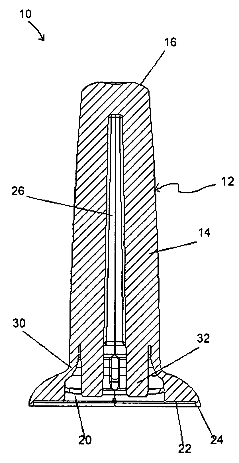
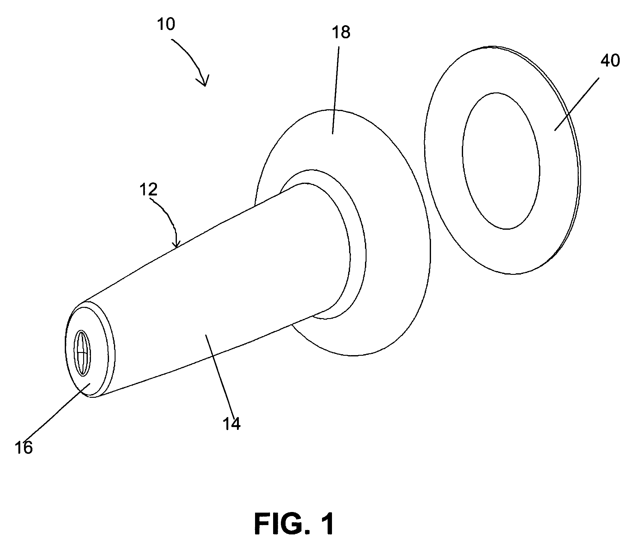
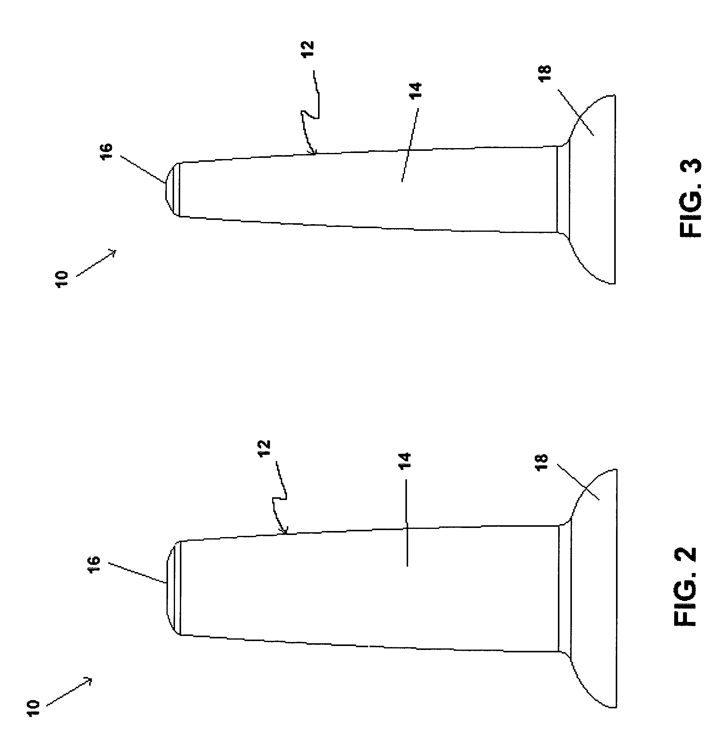
[0024]Referring now to the drawings, exemplary embodiments of a flexible doorstop, indicated generally by the numeral 10, are shown therein. The doorstop 10 comprises a unitary body 12 made of a resilient material such as a natural or synthetic rubber, or a thermoplastic elastomer. The unitary body 12 comprises a tapered shank 14 with an oval cross section, a convex tip 16 for engaging a door that swings back toward a wall surface, and a base 18 for mounting the doorstop 10 on a wall surface adjacent a doorway. Doorstop 10 may be mounted to the wall surface, for example, by means of a double-sided adhesive disk 40 that adheres to a bottom surface 22 of the base 18 and to the wall surface.

[0025]FIGS. 1 through 8 illustrate a first embodiment of the doorstop 10. In this embodiment, an air chamber 20 is formed in the unitary body as shown in FIGS. 6 and 7. The air chamber 20 extends from the base 18 into the elongate shank 14. The shank 14 may also have an axial bore 26 extending from ...


PUM


Abstract

A doorstop comprises a unitary body made of a resilient material including an elongate shank having a longitudinal axis, a tip at one end of said elongate shank, and a base at the opposite end of said elongate shank. A flexible wall connects said elongate shank to said base and is designed to flex in response to impact by a door along the longitudinal axis to absorb the impact of said door.

Description

BACKGROUND OF THE INVENTION[0001]The present invention relates generally to doorstops for preventing a door from swinging back against a wall, and more particularly, to a flexible, wall mounted doorstop to absorb the impact of the swinging door.[0002]One conventional type of doorstop comprises a rigid shank with a cushioned top at one end and a screw at the other end adapted to be threaded into the wall. Such rigid doorstops have a number of disadvantages. If the door swings back against the wall with sufficient force, the rigid doorstop may damage the door notwithstanding the cushioned tip. Further, a rigid doorstop does not yield when impacted from the side. When hit with sufficient force, the doorstop can be ripped from the wall. Another disadvantage of a conventional rigid doorstop is that the cushioned tip can sometimes separate from the shank, which increases the likelihood of damage to the door.[0003]Flexible doorstops are also known. One common type of flexible doorstop is s...

Claims


Application Information

Patent Timeline
Patent Type & Authority Patents(United States)
IPC IPC(8): E05F5/02
CPCE05F5/06Y10T16/625Y10T16/61
Inventor FORREST, PAUL BRADLEY
Owner FORREST PAUL BRADLEY
Why Eureka
Try Eureka