Sound suppressor silencer baffle

a technology of sound suppressor and baffle, which is applied in the field of baffle, can solve the problems of affecting the efficacy of firearm use, affecting the sound quality of firearms, and loss of projectile power, so as to reduce the amount of noise and reduce the sound and flash levels

Active Publication Date: 2008-08-19
VAIS GEORGE
View PDF13 Cites 57 Cited by
  • Summary
  • Abstract
  • Description
  • Claims
  • Application Information

AI Technical Summary

Benefits of technology

[0008]The present invention is a baffle for use in a sound suppressor for a firearm that reduces the sound and flash levels that are typically created when the firearm is discharged. The baffle of the present invention has a novel and unique design which enables the aforementioned aims to be achieved. The baffle of the present invention is made up of a hollow, central core-defining tube which is configured to allow passage of a projectile through the core. The hollow central core defining tube extends from a front end backwards to an intersection with an inside surface of a rear wall. This tube also extends from said front end backward to an intersection, a forward bulkhead; the tube defining a generally longitudinal slot therein. The bulkhead and the inside surface of the rear wall located in different vertical planes. In the preferred embodiment of the invention, this bulkhead and the rear wall of the baffle are connected to a generally circumvolving outer wall which defines an upper and a lower expansion chamber. An elongated slot defined within the rear wall allows passage of same material through the rear wall. These expansion areas allow for expansion of gasses after the firing of a firearm and the surfaces within these chambers provide surfaces upon which reflection of this energy can take place. The interaction of the propellant gasses against these surfaces causes these propellant gasses to hit, divide, be redirected and channeled in a way that greatly reduces the amount of noise that is perceived by a user upon the firing of a gun.
[0010]The structure of the present invention redirects gasses in a way whereby a sufficient quantity of gas traveling behind the projectile is maintained so as to minimize any decrease in power or accuracy while at the same time dissipating sufficient energy so as to significantly reduce the quantity of noise and flash that occurs with the discharge of the firearm, as compared to other sound suppressors which exist in the prior art.

Problems solved by technology

It is the rush of these propellant gasses out of the end of the firearm that cause the loud sound that results from the firing of the gun to occur.
However with the use of a sound suppressor, a variety of other side effects may result which alter the efficacy of the use of the firearm.
Some of the problems which exist and which result from the use of a sound suppressor include a loss of power to the projectile which is fired.
This loss in power can detrimentally affect the power and trajectory of the projectile which is fired from the firearm, this in turn causes problems related to the accuracy of the firearm with the sound suppressor in place.
Furthermore, the structure of some of the prior art suppressor devices are so delicate so as to limit or prevent the use of such devices in various environments.
In addition, the particular design of the firearm can have various results related to the quantity of noise which is actually reduced.

Method used


Image

  • Sound suppressor silencer baffle
  • Sound suppressor silencer baffle
  • Sound suppressor silencer baffle

Examples


Embodiment Construction

[0018]While the invention is susceptible of various modifications and alternative constructions, certain illustrated embodiments thereof have been shown in the drawings and will be described below in detail. It should be understood, however, that there is no intention to limit the invention to the specific form disclosed, but, on the contrary, the invention is to cover all modifications, alternative constructions, and equivalents falling within the spirit and scope of the invention as defined in the claims.

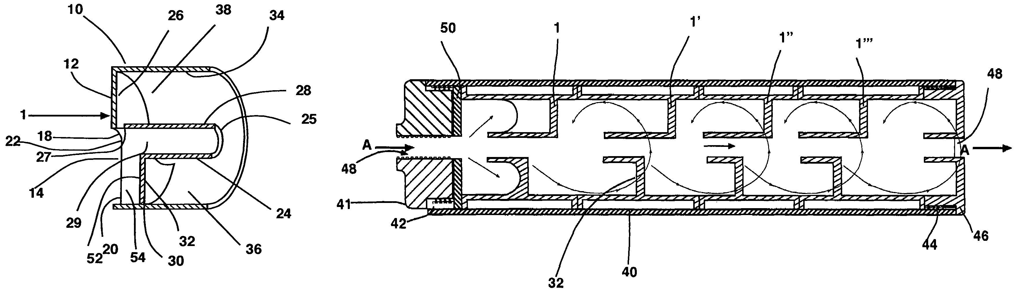
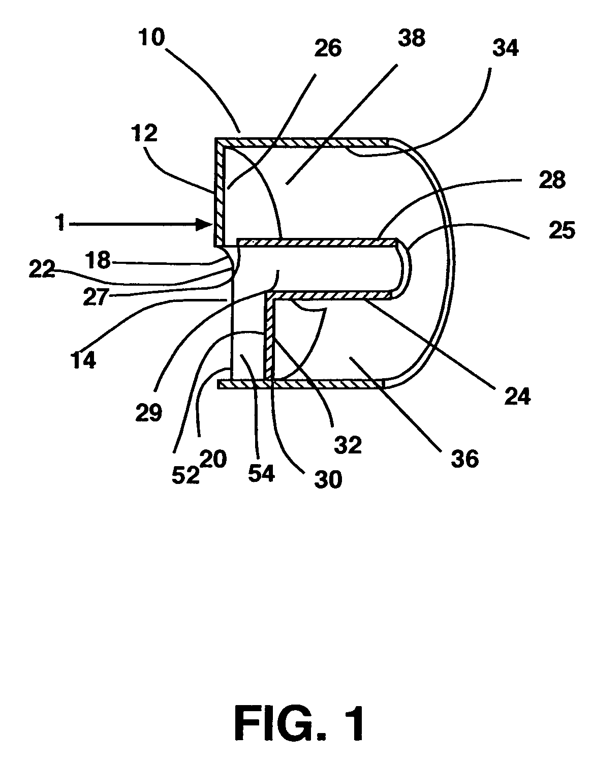
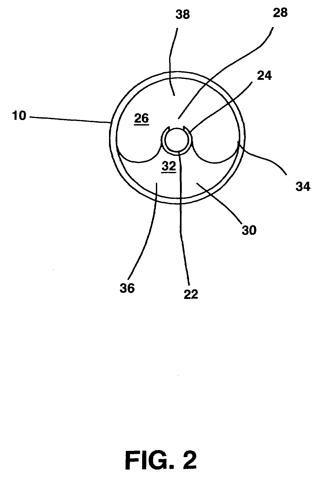
[0019]FIGS. 1-4 show various views of the preferred embodiment of the present invention. FIG. 5 shows a cut away view of the baffles of the present invention in use within a housing. Referring first to FIG. 1. FIG. 1 is a cut away cross-sectional view of the baffle 1 of the present invention showing this baffle being cut in half. The baffle 1 of the present invention is comprised of a central core defining tube 24 that extends from a front end 25 backwards to an intersection 27 wi...


PUM


Abstract

A baffle for use in a firearm suppressor, which increases the amount of sound and flash that are perceived upon the firing of a firearm upon which a suppressor is placed without substantial alteration to the power or accuracy of the firearm upon which the suppressor is attached. The baffle is made up of a generally hollow, central core defining open topped tube that is dimensioned so as to allow passage of a projectile through this core. This tube extends from an open front end backwards to an intersection with an inside surface of a rear wall, as well as to an intersection with a forward bulkhead. The bulkhead and the inside surface of the rear wall are located in different vertical and horizontal planes and define expansion chambers and reflection surfaces that alter the escape pattern of gasses out of the suppressor.

Description

CROSS-REFERENCE TO RELATED APPLICATIONS[0001]This application claims the priority date from the provisional application entitled SOUND SUPPRESSOR BAFFLE filed by the same inventor on Dec. 13, 2004 with application Ser. No. 60 / 635,323. The contents of which are herein incorporated by reference into the present application.FIELD OF THE INVENTION[0002]The invention generally relates to sound suppressors for firearms and more particularly to a baffle for use in such a sound suppressor.BACKGROUND OF THE INVENTION[0003]Sound suppressors for firearms are well known in the prior art and a variety of designs for such devices exist. The aim of a sound suppressor is to reduce the sound that emanates from the firing of a bullet from a firearm. This is typically done in most sound suppressors by reducing the pressure of the propellant gases which immediately follow the projectile out of the end of the firearm. It is the rush of these propellant gasses out of the end of the firearm that cause the...

Claims


Application Information

Patent Timeline
Patent Type & Authority Patents(United States)
IPC IPC(8): F41A21/30
CPCF41A21/30
Inventor VAIS, GEORGE
Owner VAIS GEORGE
Why Eureka
Try Eureka