Sound and flash suppressor for firearms

a suppressor and sound technology, applied in the direction of weapons, weapon components, etc., can solve the problems of many different internal parts that are difficult to assemble, require constant replacement, and do not significantly reduce muzzle flash of firearm suppressors, so as to reduce the volume of gases, reduce the level of sound and flash, and reduce the effect of flash

Inactive Publication Date: 2013-03-19
SHAND RONNIE ALEXANDER
View PDF1 Cites 18 Cited by
  • Summary
  • Abstract
  • Description
  • Claims
  • Application Information

AI Technical Summary

Benefits of technology

[0014]The present invention is a firearm suppressor that uses a vacuum chamber that reduces the sound and flash levels that are typically created when a firearm is discharged. The vacuum chamber of the present invention has adds a novel feature to firearm suppressors that enables the propellant gases to fill the vacuum chamber and by this way to remain inside the suppressor for a longer period of time. The principal object of the present invention is that the vacuum chamber diminishes the volume of gases that exit the muzzle of the firearm caused by discharging the firearm. Another objective of the present invention is to reduce flash at the muzzle. Another objective of the present invention is to reduce the pressure wave caused at the end of the firearm's barrel.
[0021]In another embodiment of the present invention different types of vacuum seals are described to show that the vacuum seal can have any shape as long as it provides a good vacuum seal and at the same time it can be perforated with ease by the exiting bullet.

Problems solved by technology

In addition, most prior art firearm suppressors do not significantly reduce muzzle flash.
Also, some prior suppressor inventions require many different internal parts that are difficult to assemble and require constant replacement.
However, the use of these shoulders with annular shoulders was used together with other methods and these conical baffles were located only in the area of the exit of the bullet from the suppressor.

Method used


Image

  • Sound and flash suppressor for firearms
  • Sound and flash suppressor for firearms
  • Sound and flash suppressor for firearms

Examples


Embodiment Construction

[0038]Embodiments of firearm suppressors for reducing the muzzle blast and muzzle flash are described. While my invention is susceptible of several variations and modifications, it should be clear that there is no intention to limit the invention to the specific forms disclosed in the drawings, but on the contrary, my invention is to cover any modifications, variations, alternative constructions, and equivalent methods of using vacuum falling within the spirit and scope of my invention.

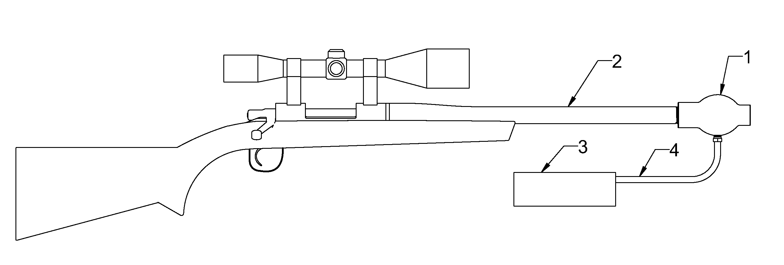
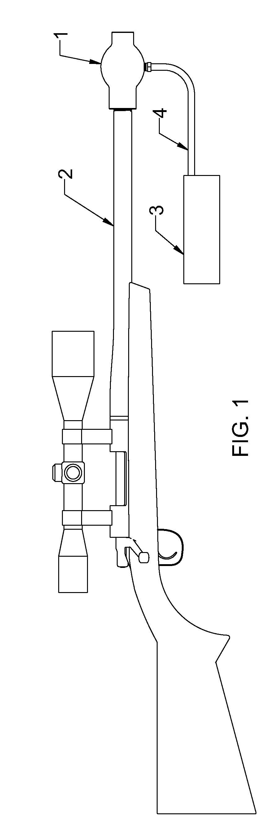
[0039]Referring now to FIG. 1, an embodiment of a rifle is shown to which an embodiment of a suppressor 1 is attached to the barrel 2. A portable vacuum generator 3 or vacuum pump 3 is connected to the suppressor 1 by a suction tube 4. Although a rifle type of firearm is shown on FIG. 1, embodiments of my invention may be used with other types of weapons such as cannons or hand guns. Although the vacuum pump 3 is shown as a separate component from the suppressor 1, it can also be constructed as an int...


PUM


Abstract

A gun suppressor having a single or multiple vacuum chambers that create a vacuum enclosed volume for gases to expand into. Accordingly, the pressure of the gas that exits the suppressor is reduced significantly; therefore, the sound of the gun firing is more silent than conventional silencers. Prior to firing the gun, a vacuum seal is placed at the exit orifice of the suppressor and a vacuum is created inside of the suppressor with the use of a vacuum pump. The vacuum chamber reduces the pressure wave caused at the end of the firearm's barrel. When the firearm is discharged, the gases fill the vacuum chamber instead of exiting at normal atmospheric pressure level. As the bullet continues its travel through the end of the suppressor, it perforates the vacuum seal and continues its flight path.

Description

CROSS-REFERENCE TO RELATED APPLICATIONS[0001]This application is a continuation of Ser. No. 61 / 370,455 filed on Aug. 4, 2010, by the same inventor Ronnie Alexander Shand.BACKGROUND[0002]1. Field of the Invention[0003]The present invention relates to a sound and flash suppressor for a firearm, and more particularly to reduce the noise caused by the firing of a firearm comprising a silencer muffler which attenuates explosive sounds generated by firearms and which have a straight-through passage for the projectile and silencing chambers for the explosive exhaust.[0004]2. Background of the Invention[0005]Sound suppressors for firearms are well known in the prior art, and many have been patented over a hundred years.[0006]Many different techniques have been created and patented, chambers, gas passages and baffles of varying designs have been extensively used. The purpose of a sound and flash suppressor, regardless of the technique used, is to reduce the exit pressure and velocity of the ...

Claims


Application Information

Patent Timeline
Patent Type & Authority Patents(United States)
IPC IPC(8): F41A21/30
CPCF41A21/30
Inventor SHAND, RONNIE ALEXANDER
Owner SHAND RONNIE ALEXANDER
Why Eureka
Try Eureka