Devices, systems and methods for testing gas sensors and correcting gas sensor output

a technology of gas sensor and output, applied in the direction of liquid/fluent solid measurement, electrochemical variables, instruments, etc., can solve the problems of self-consistent, analytically incorrect indication of sensor health, complex and ambiguous,

Active Publication Date: 2008-08-19
MSA TECH
View PDF13 Cites 75 Cited by
  • Summary
  • Abstract
  • Description
  • Claims
  • Application Information

AI Technical Summary

Benefits of technology

[0017]The method of testing or interrogation of a sensor and subsequent correction of sensor output of the present invention provides a real-time measure of sensor performance. The electronic interrogation exercises or effects the sensor in generally the same way that exposure to target gas does. That is, the test method of the present invention measures the ability of the sensor to respond to or comply with a current demand between the working electrode and the counter electrode. The appearance of target gas at the working electrode results in a demand for a current to flow, internally, through the sensor. This flow of current involves faradaic movement of electrons across the phase boundary regions of the working electrode and the counter electrode and ionic current flow through the electrolyte of the sensor. The test method of the present invention causes current to flow through the sensor in the same manner. However, the magnitude of the current demand imposed by the interrogation method of the present invention is fixed as a function of the electronic components through which it is imposed. Therefore, the response function of the sensor varies only as a function of age, environmental exposure, or other internal variables of the sensor.

Problems solved by technology

However, the technique has several disadvantages including, for example, complexity and ambiguity.
Moreover, unless some method of monitoring the condition of the gas generator is employed, these methods can result in a self-consistent, but analytically incorrect indication of sensor health.

Method used


Image

  • Devices, systems and methods for testing gas sensors and correcting gas sensor output
  • Devices, systems and methods for testing gas sensors and correcting gas sensor output
  • Devices, systems and methods for testing gas sensors and correcting gas sensor output

Examples


Embodiment Construction

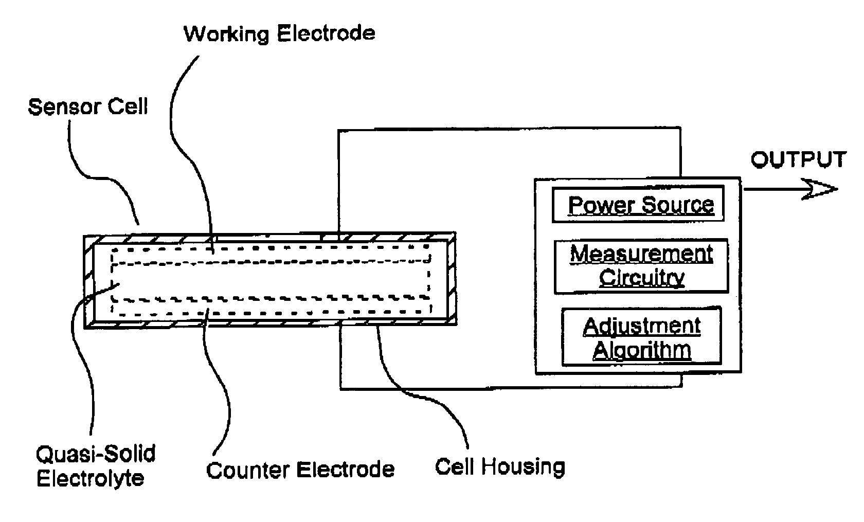
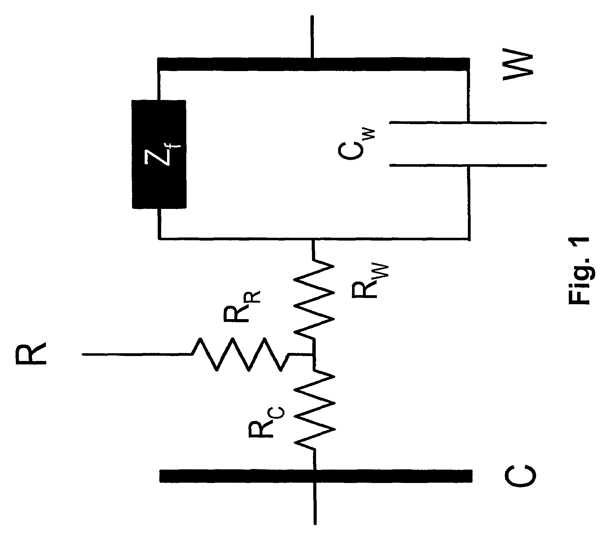
[0032]As a result of its structure, a fuel cell-type electrode can be modeled by reference to common analog electronic components, such as resistors and capacitors. An equivalent circuit that is commonly used to describe the behavior of electrochemical cells is shown in FIG. 1. See, for example, P. T. Kissinger and W. R. Heineman, eds., Laboratory Techniques in Electroanalytical Chemistry, New York: Marcel Dekker, Inc. (1984) and A. J. Bard and L. R. Faulkner, Electrochemical Methods: Fundamentals and Applications, New York: John Wiley and Sons (1980).

[0033]As illustrated in FIG. 1, a sensor can be described as resistance and capacitance in series. The resistance RR resulting from the reference electrode of FIG. 1 is not part of the current path of the analytical signal of the sensor. The resistive portion of this circuit is primarily a result of the solution (ionic) resistance of the electrolyte interspersed between the working electrode (RW) and the counter electrode (RC). The cap...


PUM

PropertyMeasurementUnit
currentaaaaaaaaaa
voltageaaaaaaaaaa
surface-areaaaaaaaaaaa

Abstract

A method of adjusting the output of an electrochemical sensor includes the steps of: simulating the presence of an analyte gas electronically; measuring a response of the sensor to the electronic simulation; and adjusting the output of the sensor as a function of the measured response to the electronic simulation. The method of adjusting the output of an electrochemical sensor having a working electrode and a counter electrode preferably includes the steps of: electronically causing a current flow between the working electrode and the counter electrode; measuring a response of the sensor to the current demand; and using the measured response to adjust the sensor output during sampling of an analyte gas.

Description

FIELD OF THE INVENTION[0001]The present invention relates generally to devices, systems and methods for testing gas sensors, and, more particularly, to devices, systems and methods for testing gas sensors electronically and correcting the output of the gas sensor on the basis of the electronic test.BACKGROUND OF THE INVENTION[0002]Amperometric or fuel cell-type gas sensors typically include at least two electrocatalytic electrodes (an anode and a cathode), at least one of which is a gas diffusion electrode or working electrode. The working electrode can be either the anode or the cathode in any given sensor. The gas diffusion electrode typically includes fine particles of an electrocatalytic material adhered to one side of a porous or gas-permeable membrane. The gas sensor can also include a third, reference electrode to maintain the working electrode at a known voltage or potential.[0003]The electrocatalytic side of the working electrode is in ionic contact with the second electrod...

Claims


Application Information

Patent Timeline
Patent Type & Authority Patents(United States)
IPC IPC(8): G01N27/26G01N27/416G01N27/417G01N33/00
CPCG01N33/0006G01N27/404Y02E60/50
Inventor SCHEFFLER, TOWNER B.
Owner MSA TECH
Why Eureka
Try Eureka