Coil apparatus and nuclear magnetic resonance apparatus using the same
a technology of nuclear magnetic resonance and coil, applied in the field of coil, can solve the problems of reducing the productivity of coils, increasing the loss, and prolonging the irradiation time, and achieve the effect of large degree of freedom in design and simple configuration
- Summary
- Abstract
- Description
- Claims
- Application Information
AI Technical Summary
Benefits of technology
Problems solved by technology
Method used
Image
Examples
examples
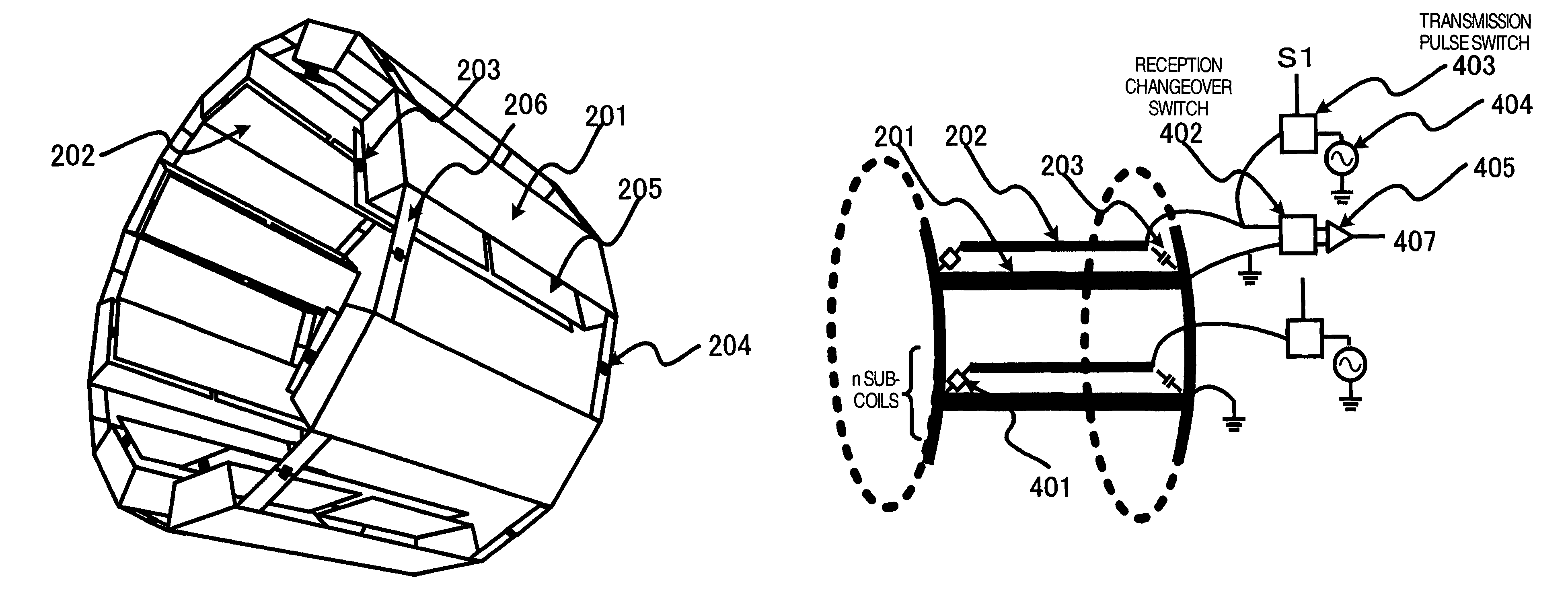
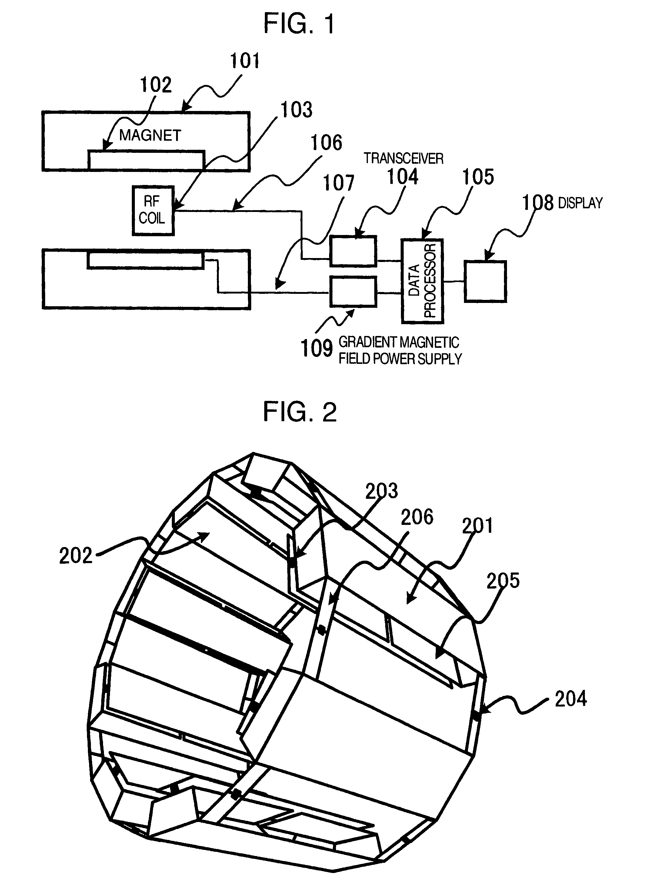
[0074]Hereafter, examples of the case where an RF coil has a shape including eight subcoils as shown in FIG. 2 is applied to the multi-channel transmission / one-channel reception and the one-channel transmission / multi-channel reception will be described. Coil design in the examples described hereafter is based upon results obtained by conducting simulation on an RF coil having a length in the axial direction of approximately 220 mm, an outside diameter of approximately 340 mm, and an inside diameter of approximately 270 mm.
first example
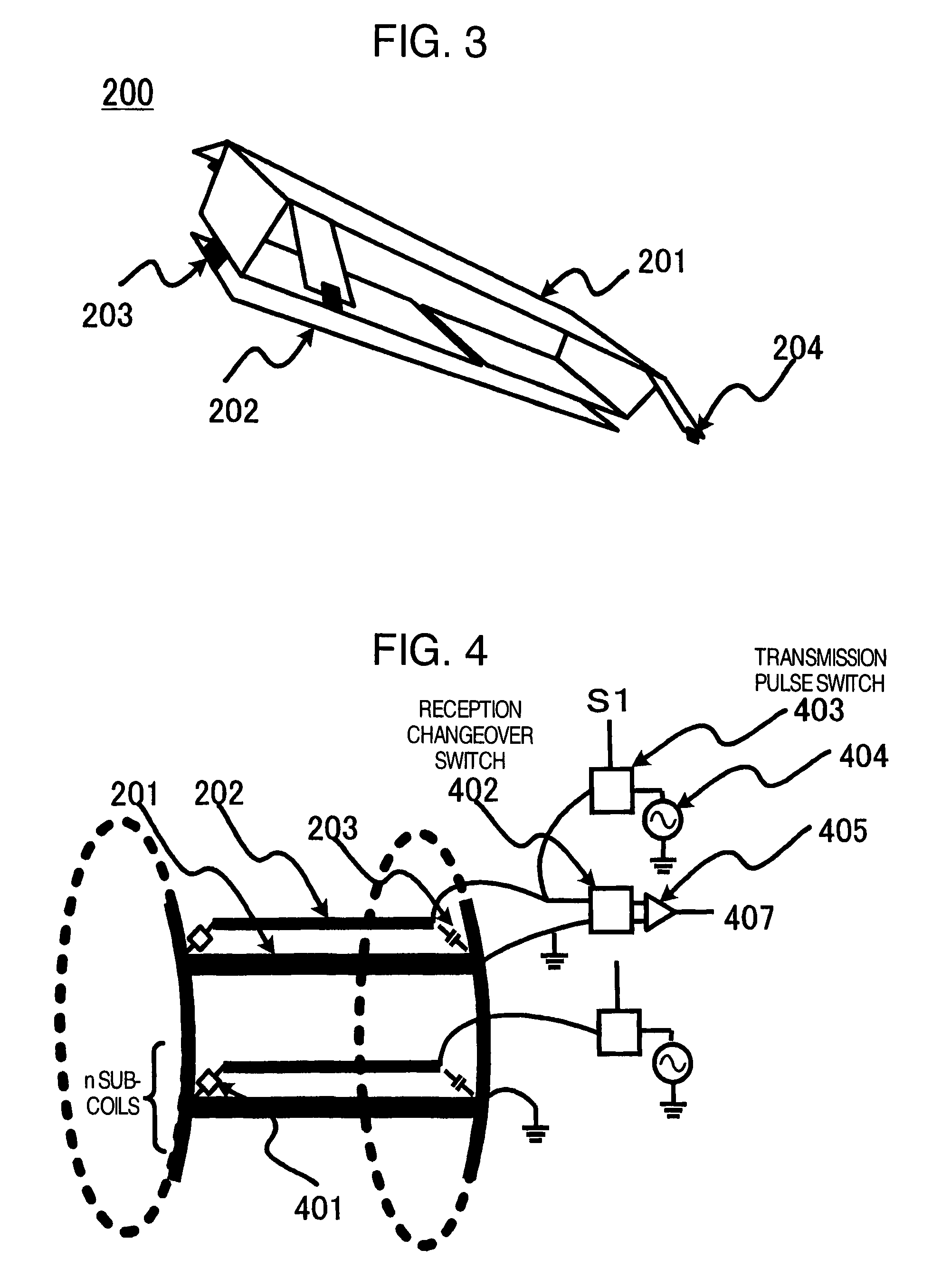
[0075]First, resonance characteristics of an RF coil having a shape including eight subcoils are found by simulation. Results are shown in FIG. 12. In FIG. 12, the abscissa indicates the frequency and the ordinate indicates resonance impedance. As indicated by a graph 601, a plurality of peaks appear in resonance characteristics in the one-channel mode. There is a property that the number of peaks becomes equal to (the number of subcoils / 2+1). In the RF coil including eight subcoils, the number of peaks becomes five. At a resonance peak having a second lowest frequency among five peaks arranged on a frequency axis, the sensitivity is obtained most uniformly within the coil cylinder. In the coil design, therefore, it is necessary to determine the capacitance of the capacitor 203 between conductors and the capacitance of the capacitance changeover capacitor 401 so as to make both the resonance peak 602 in the multi-channel mode and the second resonance peak in the one-channel mode equ...
second example
[0079]In the one-channel transmission / multi-channel reception RF coil shown in FIG. 8, the resonance peak in the multi-channel mode and the second resonance peak in the one-channel mode shown in FIG. 12 are set nearly equal to 126 MHz which is the resonance frequency of hydrogen nuclei in the MRI apparatus of 3 Tesla. In this case, the capacitance of the inter-conductor capacitor 203 and the capacitance of the capacitance changeover capacitor 401 are found by simulation. In the one-channel transmission / multi-channel reception RF coil, the inter-subcoil conduction control circuit 204 is added between the first conductors unlike the multi-channel transmission / one-channel reception RF coil.
[0080]Since the conduction between subcoils is limited by the inter-subcoil conduction control circuit 204, the resonance peak in the case of the multi-channel mode (the case of the single peak 602) shifts to the low frequency side. As a result, it becomes possible in the second example as well to us...
PUM
 Abstract
Description
Claims
Application Information
 - R&D
- Intellectual Property
- Life Sciences
- Materials
- Tech Scout
- Unparalleled Data Quality
- Higher Quality Content
- 60% Fewer Hallucinations
Browse by: Latest US Patents, China's latest patents, Technical Efficacy Thesaurus, Application Domain, Technology Topic, Popular Technical Reports.
© 2025 PatSnap. All rights reserved.Legal|Privacy policy|Modern Slavery Act Transparency Statement|Sitemap|About US| Contact US: help@patsnap.com


