Connector and manufacturing method of the same

a technology of connecting parts and manufacturing methods, applied in the direction of coupling contact members, coupling device connections, securing/insulating coupling contact members, etc., can solve the problems of low pressing force of elastic members, low waterproof function, low etc., to improve the free design of circuits and improve the waterproof performance of drawing out portions

Active Publication Date: 2019-11-12
YAZAKI CORP
View PDF30 Cites 10 Cited by
  • Summary
  • Abstract
  • Description
  • Claims
  • Application Information

AI Technical Summary

Benefits of technology

[0007]In the connector disclosed in Patent Literature 1, the airtightness between the holder and the drawing-out portion of the housing is low, and there is a possibility that water or the like may intrude into the drawing-out portion from the flat cable side.
[0012]It is therefore an object of the present invention to provide a connector and a manufacturing method of a connector which can improve the waterproof performance of a drawing-out portion side of a housing and can improve the free design of circuit.
[0045]According to the present invention, it is possible to provide a connector and a manufacturing method of a connector which can improve the waterproof performance of a drawing-out portion side of a housing and can improve the free design of circuit.

Problems solved by technology

In the connector disclosed in Patent Literature 1, the airtightness between the holder and the drawing-out portion of the housing is low, and there is a possibility that water or the like may intrude into the drawing-out portion from the flat cable side.
However, the pressing force of the elastic member is low in the waterproof function, and the waterproof performance on the drawing-out portion side is insufficient.
With this, when it is desired to connect a single terminal to plural conductors in the flat cable by circuit design, the terminal is required to have a complicated shape, and such situation has deteriorated the free design of circuit.

Method used


Image

  • Connector and manufacturing method of the same
  • Connector and manufacturing method of the same
  • Connector and manufacturing method of the same

Examples


first embodiment

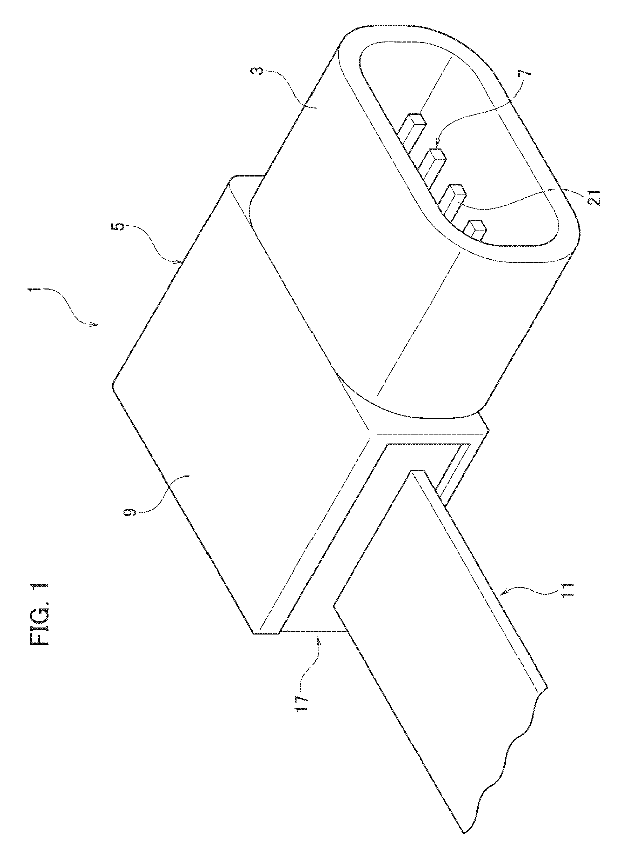
[0065]A first embodiment will be described with reference to FIGS. 1 to 8.

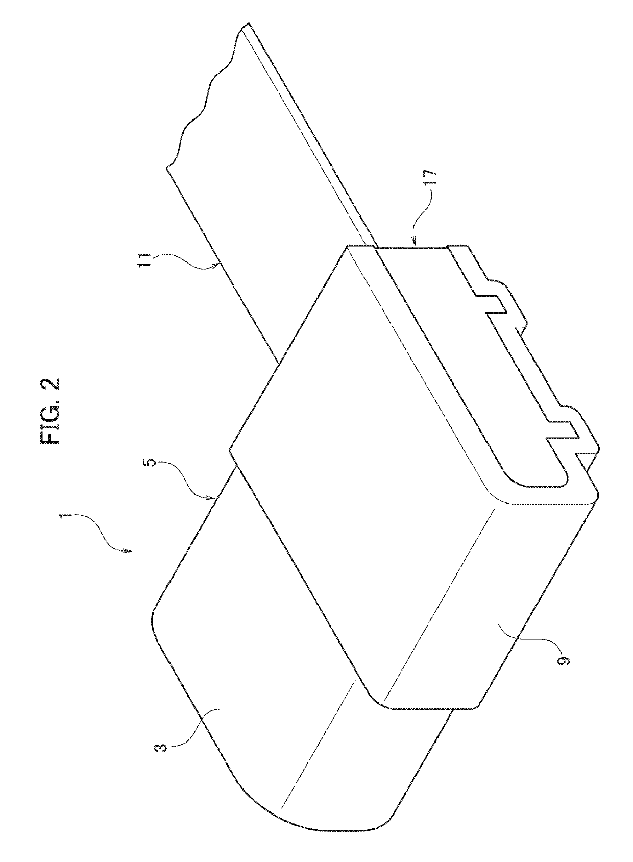
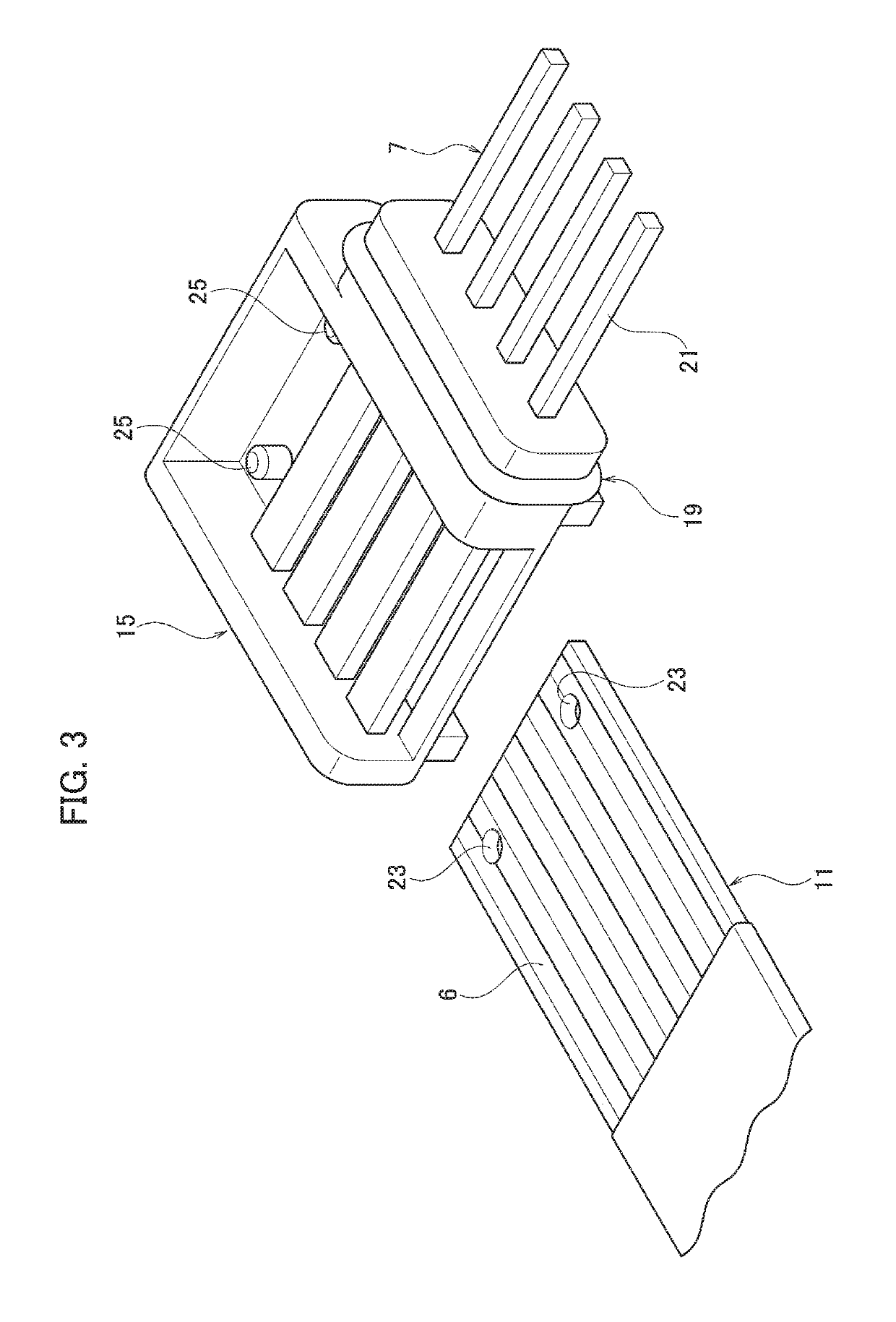
[0066]A connector 1 according to the present embodiment includes: a housing 5 including a fitting portion 3 capable of being fitted with an opponent housing; terminals 7 accommodated in the housing 5, one end side of each terminal 7 being arranged in the fitting portion 3; a flat cable 11 drawn out of a drawing-out portion 9 of the housing 5, provided with conductors connected to the other end of each terminal 7, the conductors being formed along a longitudinal direction of the flat cable 11 and arranged in a width direction of the flat cable 11; and a holder 15 integrally provided with the terminal 7 on the other end side of each terminal 7, accommodated in the drawing-out portion 9, in which a connection portion 13 of the terminals 7 and the flat cable 11 is arranged.

[0067]The flat cable 11 is draw out of the drawing-out portion 9 in a direction orthogonal to a fitting direction in which the housing 5 and th...

second embodiment

[0128]A second embodiment will be described with reference to FIGS. 9 to 13.

[0129]In a connector 101 according to the present embodiment, a first sealing material 103 covering the connection portion 13 is integrally provided with the holder 15 around the connection portion 13 in the holder 15.

[0130]Plural holders 15 are accommodated in the drawing-out portion 9. The first sealing material 103 is integrally provided with the holders 15 around the holders 15 to hold the holders 15.

[0131]In a manufacturing method of the connector 101, before the holders 15 are accommodated in the drawing-out portion 9, the first sealing material 103 covering the connection portion 13 is integrally formed with the holder 15 around the connection portion 13 in the holder 15.

[0132]Further, before the holders 15 are accommodated in the drawing-out portion 9, the holders 15, in each of which the connection portion 13 is formed, are stacked to each other, and the first sealing material 103 is integrally form...

first modification

of Second Embodiment

[0152]A first modification of the second embodiment will be described with reference to FIGS. 9 to 13.

[0153]In the connector 101 according the present modification, the sealing material includes the first sealing material 103. The first sealing material 103 is formed to be capable of closing the drawing-out portion 9 and to be capable of being welded to the inner periphery of the drawing-out portion 9.

[0154]In a manufacturing method of the connector 101 according to the first modification, the first sealing material 103 covering the connection portion 13 and being capable of closing the drawing-out portion 9 and being welded to the inner periphery of the drawing-out portion 9, is integrally formed with the holder 15 around the connection portion 13 in the holder 15. The holder 15 is accommodated in the drawing-out portion 9 of the housing 5. The flat cable 11 is drawn out of the drawing-out portion 9 toward the outside of the housing 5 in the direction orthogonal...


PUM


Abstract

A connector includes: a housing with a fitting portion; a terminal accommodated in the housing, one end side of the terminal being arranged in the fitting portion; a flat cable drawn out of a drawing-out portion of the housing, provided with conductors connected to the other end of the terminal; and a holder integrally provided with the terminal on the other end side of the terminal, accommodated in the drawing-out portion, in which a connection portion of the terminal and the flat cable is arranged. The flat cable is draw out of the drawing-out portion in a direction orthogonal to a fitting direction of the housing. The terminal is placed across the conductors at the connection portion. The drawing-out portion is closed with a sealing material. The sealing material is integrally provided with an inner periphery of the drawing-out portion and an outer periphery of the flat cable.

Description

CROSS REFERENCE TO RELATED APPLICATIONS[0001]The present application claims priority to Japanese Patent Application No. 2017-093685 filed on May 10, 2017, the entire contents of which are incorporated by reference herein.BACKGROUND1. Technical Field[0002]The present invention relates to a connector and a manufacturing method of the same, particularly to a connector having a drawing-out portion of a housing from which a flat cable is drawn out and a manufacturing method of the same.2. Description of the Related Art[0003]There has been known a conventional connector including: a housing provided with a fitting portion to be fitted with an opponent housing; terminals accommodated in the housing, one ends of which are disposed at the fitting portion; a flexible printed circuit as a flat cable drawn out of a joint part housing hole as a drawing-out portion of the housing toward the outside, including conductors connected with the other ends of the terminals, the conductors formed along a...

Claims


Application Information

Patent Timeline
Patent Type & Authority Patents(United States)
IPC IPC(8): H01R12/77H01R43/18H01R13/52
CPCH01R12/774H01R12/777H01R13/5208H01R43/18H01R13/5216H01R12/771H01R13/02H01R13/40H01R13/405H01R13/5202H01R13/5205H01R13/521H01R43/00H01R43/20
Inventor TSUBAKI, AKIRA
Owner YAZAKI CORP
Why Eureka
Try Eureka