Switching arrangement and method with separated output buffers

a technology of output buffers and switching arrangements, applied in data switching networks, store-and-forward switching systems, time-division multiplexing selection, etc., can solve the problems of increased delays or even information loss, packet switches that rely solely on output queuing, and are not well scalable to high data rates. , the effect of facilitating circuit design

Active Publication Date: 2010-12-07
IBM CORP
View PDF26 Cites 10 Cited by
  • Summary
  • Abstract
  • Description
  • Claims
  • Application Information

AI Technical Summary

Benefits of technology

[0010]It is an advantage of the invention according to the claims that the switching arrangement is less expensive than other switching arrangement with comparable performance because the output router function is substituted by a multiplication of output buffer space which is much cheaper than the space needed for an output router. Output routers need an extraordinary amount of wiring which is not necessary for memory. Furthermore the logic circuitry for processing the data packets becomes less complex which facilitates circuit design.
[0011]A switch input queue can be arranged for queuing therein the data packets arriving at the input port. Such a queue has the advantage that it can buffer the data packets whereby for each data packet only one copy is stored instead of multiple copies in the output buffers.
[0012]An address manager can be arranged for managing the use of the addresses of the output buffer, and an output queue router can be used for entering the addresses at which the data packets are stored in the output buffer, into the output queues.
[0013]A bypass for leading the payload directly from the input port to its multiplexer has the advantage that the data packets can be processed without using the output buffers, an address and the output queues. This saves time, reduces system usage and the risk of backpressure.
[0014]A congestion detector can be used for allowing the data packet to be led via the corresponding bypass when the corresponding multiplexer is able to multiplex the data packet to its output port. This provides a simple solution for deciding whether a data packet can be transferred directly to the output port.
[0015]The output queues can provide in total more queuing places for the addresses than the corresponding output buffer has addresses. When the output queues have more queuing places than the output buffer has addresses, a non-equal distribution between the various input queues can be handled without losing data packets. A total unequal distribution could be buffered completely if each output queue has the number of queuing places equal to the number of addresses in the corresponding output buffer.

Problems solved by technology

The network nodes in which lines or transmission links from various directions are interconnected for exchanging information between them are often the cause of delay in the transmission.
If much traffic is concentrated in a node, and if in particular most of the traffic passes through only few of the links, increased delays or even loss of information are often encountered.
The bandwidth through the shared memory of an output-queued switch must equal N times the individual port speed, which poses significant implementation concerns at high line rates.
Packet switches that rely solely on output queuing are not well scalable to high data rates because of the high memory bandwidth requirement.
Implementations that use a high degree of parallelism can achieve the desired bandwidth, but limit the amount of memory that can be integrated on a single chip, thus potentially leading to high packet loss rates and highly traffic-dependent performance.

Method used


Image

  • Switching arrangement and method with separated output buffers
  • Switching arrangement and method with separated output buffers
  • Switching arrangement and method with separated output buffers

Examples


second embodiment

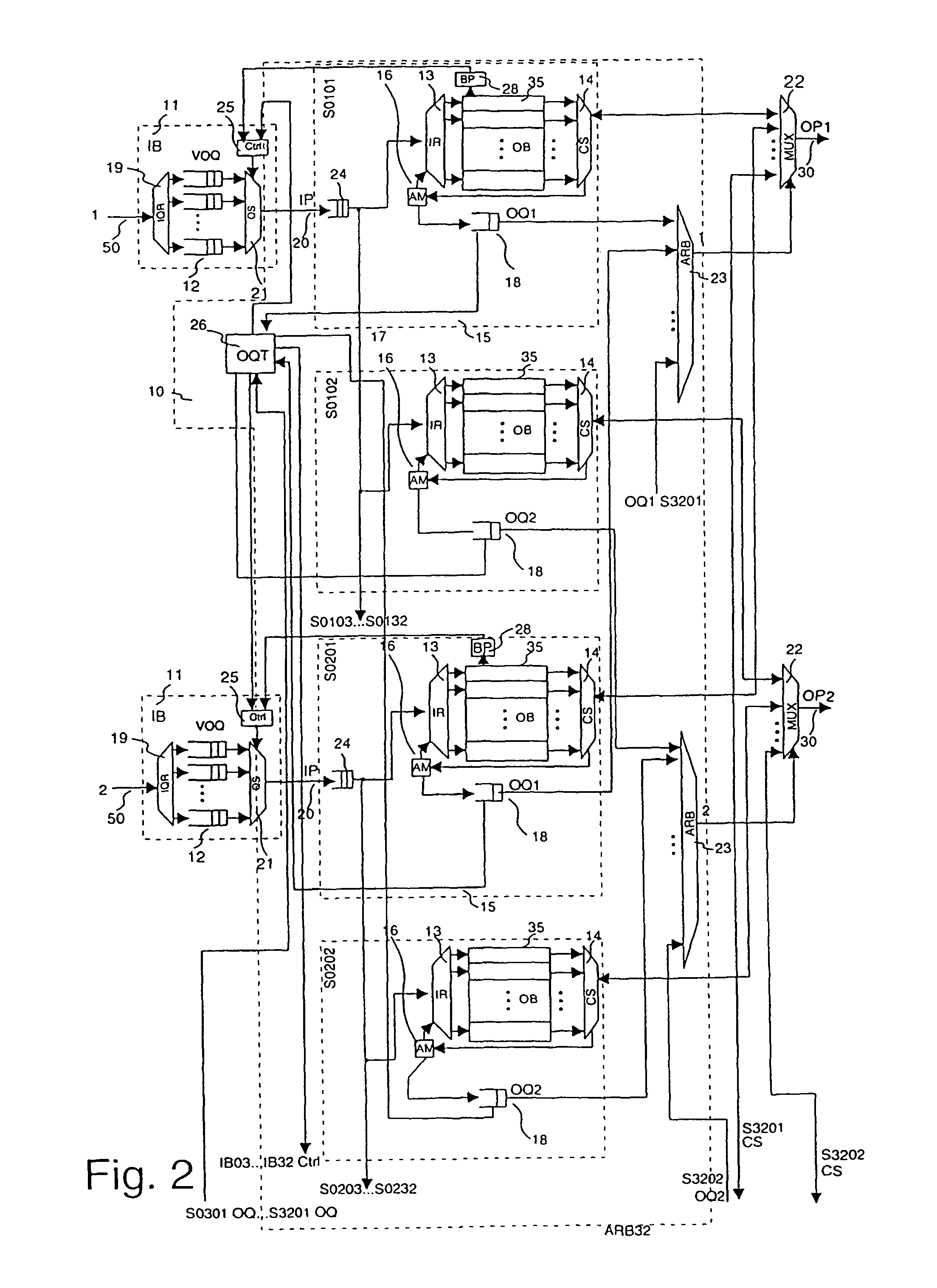
[0081]In FIG. 2, a second embodiment is depicted. It differs from the embodiment in FIG. 1 in the following respects.

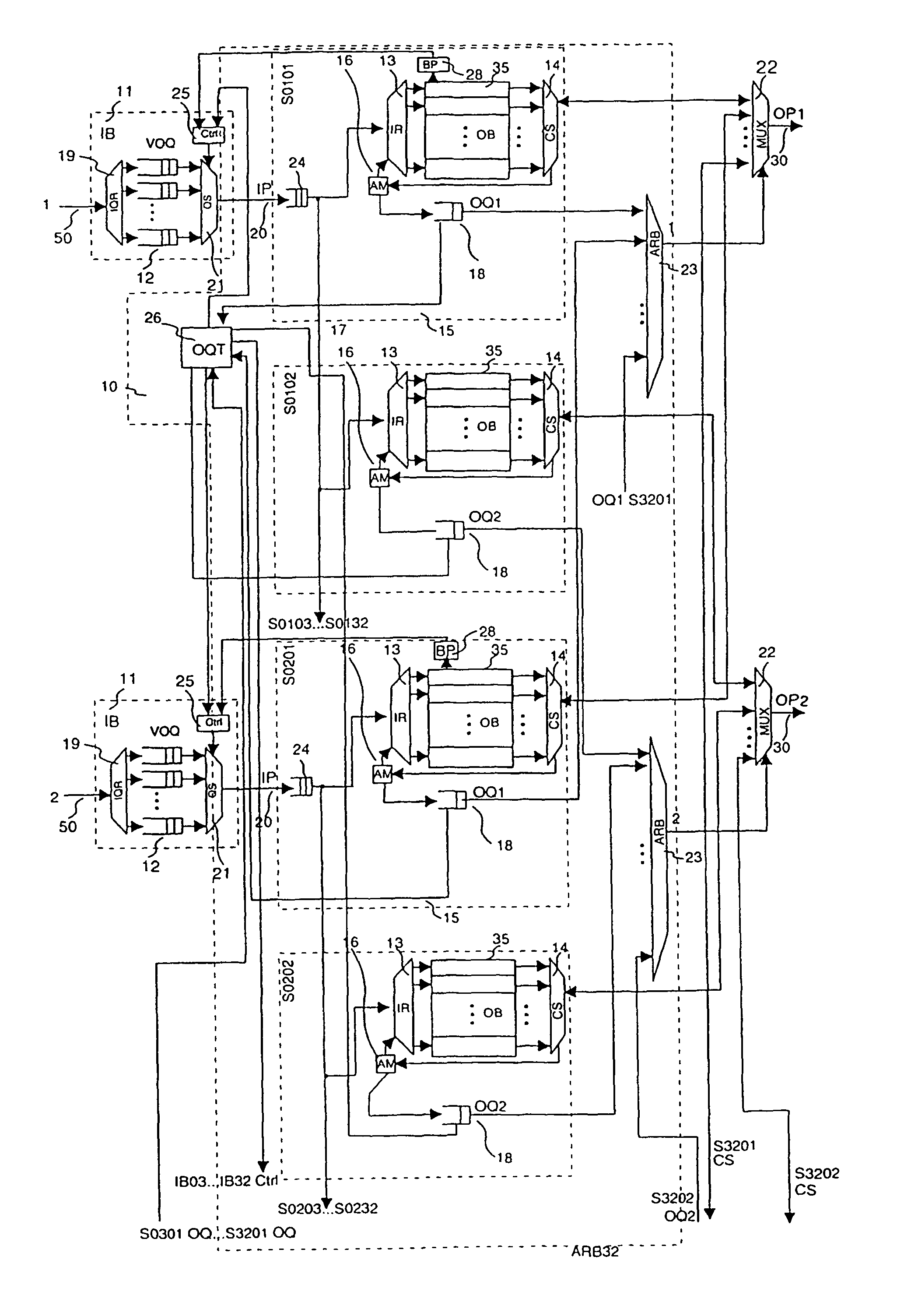
[0082]Each switching section here has its own set of output queues 18 together with a corresponding output queue router 17 and an address manager 16. Thereby each output buffer 35 is independently manageable in its address space. The address management works thereby as explained above, but each copy of the data packet that is being stored in one of the output buffers 35 of the same input port 20, receives its own address. This has the advantage that for cases of inhomogeneous destination distribution a better throughput and output buffer usage can be achieved. A typical example of such an inhomogeneity would be a burst, i.e. a series of data packets with the same destination. In the case of such a burst, the situation could occur that the first output buffer 35 assigned to the first output port 30 is occupied exclusively by data packets that head for this first output...

third embodiment

[0085]In FIG. 4 another embodiment of the invention is depicted. Herein a pairing of inputs and outputs has been utilized. The first input port 20, labelled with a “1”, and the second input port 20, labelled with a “2” are both assigned to a common switching section. This means that the input routers 13 and the output queue router 17 of that switching section receive input from both these input ports 20. The input routers 13 therefore are designed as repowering trees with two inputs. The corresponding address manager 16 handles two addresses at each point in time, one for each input port 20. At the output side of the switching section, the cell selectors 14 are designed to deliver their output to each of the multiplexers of the first output port OP1 and the second output port OP2. The second output buffer 35 of that switching section is hence via its cell selector 14 connected to the third output port OP3 and the fourth output port OP4. The rest of the output buffers 35 of that swit...


PUM


Abstract

Discloses a switching arrangement for packets of data, with several input ports and several output ports and which is determined for the transportation of incoming packets to one or more designated of the output ports and from there to a subsequent device. More particularly it relates to a switching arrangement and method wherein for each input port a set of output buffers is arranged, each set comprising an output buffer for each output port.

Description

[0001]This application claims the benefit of European Patent Application Number 01104850.1 filed on Feb. 28, 2001.TECHNICAL FIELD[0002]The invention relates to a switching arrangement for packets of data, with several input ports and several output ports and which is determined for the transportation of incoming packets to one or more designated of the output ports and from there to a subsequent device. More particularly it relates to a switching arrangement and method wherein for each input port a set of output buffers is arranged, each set comprising an output buffer for each output port. As data packets, particularly ATM cells or also Ethernet frames can be accepted.DESCRIPTION OF PRIOR ART[0003]Fast switching of information, be it samples of analog signals or alphanumeric data, is an important task in a communication network. The network nodes in which lines or transmission links from various directions are interconnected for exchanging information between them are often the cau...

Claims


Application Information

Patent Timeline
Patent Type & Authority Patents(United States)
IPC IPC(8): H04L12/28H04L12/56H04L12/54H04L49/111H04Q11/04
CPCH04L49/203H04L49/3081H04Q11/0478H04L2012/5635H04L2012/5672H04L2012/5679H04L2012/5681H04L49/25H04L49/112
Inventor BENNER, ALANENGBERSEN, ANTONIUSGOLDRIAN, GOTTFRIEDLUIJTEN, RONALD
Owner IBM CORP
Why Eureka
Try Eureka