Circuit for using capacitor voltage divider in a delta-sigma digital-to-analog converter to generate reference voltage

Active Publication Date: 2005-11-15
PRINCETON TECHNOLOGY
View PDF4 Cites 10 Cited by
  • Summary
  • Abstract
  • Description
  • Claims
  • Application Information

AI Technical Summary

Benefits of technology

[0007]The primary objective of the present invention is to provide an improved circuit design for a delta-sigma digital-to-analog converter. A delta-sigma digital-to-analog converter being conventionally provided with integrating operational amplifier, sampling capacitors, integrating capacitor, resistor voltage divider and operational amplifier buffers, wherein a reference voltage generating circuit consisted of the resistor voltage divider and the operational amplifier buffers are replaced by a capacitor voltage divider, and three trigger signals of different phases are designed to control three sets of switches, a first trigger signal only turns on a

Problems solved by technology

However, as shown in FIG. 2, to make the reference voltages Vref+, Vref− of the digital-to-analog converter 3 more accurate, it must use the operational amplifiers 21, 22 as buffers, but the problem is that the operational amplifiers 21, 22 are big,

Method used


Image

  • Circuit for using capacitor voltage divider in a delta-sigma digital-to-analog converter to generate reference voltage
  • Circuit for using capacitor voltage divider in a delta-sigma digital-to-analog converter to generate reference voltage
  • Circuit for using capacitor voltage divider in a delta-sigma digital-to-analog converter to generate reference voltage

Examples


Embodiment Construction

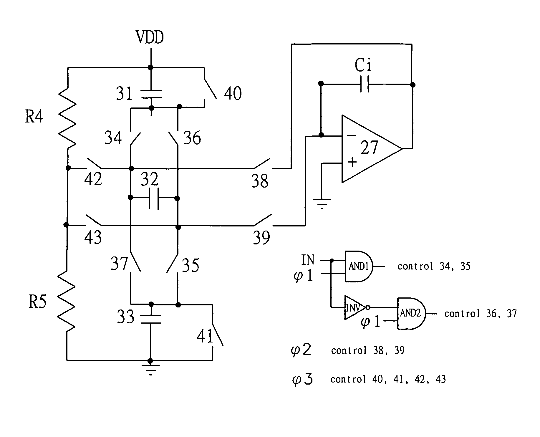
[0012]Referring to FIG. 3, a reference voltage generating circuit for a digital-to-analog converter in accordance with the present invention is shown, which comprises sampling capacitors 31, 32 and 33 that are used to replace the resistors R1, R2 and R3 in FIG. 2, ten switches 34, 35, 36, 37, 38, 39, 40, 41, 42, 43 and two resistors R4 and R5, these components are connected as shown in FIG. 3(a) and are used to replace the voltage divider circuit at the left side of the FIG. 2(a).

[0013]FIG. 3(b) is an illustrative view for showing the signals to control the switches 34, 35, 36, 37, 38, 39, 40, 41, 42 and 43, wherein the signal φ1 controls switches 34, 35, 36 and 37, the signal φ2 controls the switches 38 and 39, the signal φ3 controls the switches 40, 41, 42 and 43. The high level means that the switch is turned on, while the lower level represents the switch is turned off. The signal φ1, the input signal IN (output of the noise shaping loop 2) are inputted to AND gate 1 (AND 1), th...


PUM


Abstract

An improved circuit for a delta-sigma digital-to-analog converter comprises integrating operational amplifier, sampling capacitors, integrating capacitor, and a voltage divider consisting of a plurality of sampling capacitors. Three trigger signals of different phases are designed to control three sets of switches, a first trigger signal only turns on and off a first set of switches, so as to charge the plurality of sampling capacitors, a second trigger signal only turns on and off a second set of switches, so as to enable the charge on one of the sampling capacitor and the charge on the integrating capacitor to be averaged, a third trigger signal only turns on and off a third set of switches, to enable the plurality of sampling capacitors to be discharged.

Description

FIELD OF THE INVENTION[0001]The present invention relates to a delta-sigma digital-to-analog converter, and more particularly to an improved circuit design for using capacitor voltage dividers in a delta-sigma digital-to-analog converter to generate reference voltage.BACKGROUND OF THE INVENTION[0002]As shown in FIG. 1, which is an illustrative view for showing a delta-sigma digital-to-analog converter. The delta-sigma digital-to-analog converter comprises an interpolation filter 1, a noise shaping loop 2, a digital-to-analog converter 3 and an analog low-pass filter 4, wherein a digital signal D is inputted to the interpolation filter 1, and an analog signal A is outputted from the analog low-pass filter 4.[0003]FIG. 2(a) shows a circuit diagram of the digital-to-analog converter 3, located at the left side of which is the circuit for generating reference voltage, including resistors R1, R2, R3 and operational amplifiers 21, 22 which are electrically connected as shown. The generate...

Claims


Application Information

Patent Timeline
IPC IPC(8): H03M3/00H03M1/00H03M1/06H03M1/66H03M7/00
CPCH03M3/502
Inventor HSU, CHI-LIN
Owner PRINCETON TECHNOLOGY
Why Eureka
Try Eureka