Distributed amplifier topologies with improved gain bandwidth product

a technology of amplifiers and topologies, applied in the direction of amplifiers with transit-time effects, amplifiers with semiconductor devices/discharge tubes, amplifiers with coupling networks, etc., can solve the problem of limited number of unit cells that can be usefully used, and achieve the simplest possible structure of the unit cells involved, the effect of increasing the product of gain and bandwidth

Inactive Publication Date: 2008-08-19
ATMEL CORP
View PDF8 Cites 4 Cited by
  • Summary
  • Abstract
  • Description
  • Claims
  • Application Information

AI Technical Summary

Benefits of technology

[0014]It is therefore an object of the present invention to provide a distributed amplifier with an increased product of gain and bandwidth and with the simplest possible structure of the unit cells involved.

Problems solved by technology

In reality, however, the number of unit cells that can usefully be employed is limited by the aforementioned losses in the input and output networks.

Method used


Image

  • Distributed amplifier topologies with improved gain bandwidth product
  • Distributed amplifier topologies with improved gain bandwidth product
  • Distributed amplifier topologies with improved gain bandwidth product

Examples


Embodiment Construction

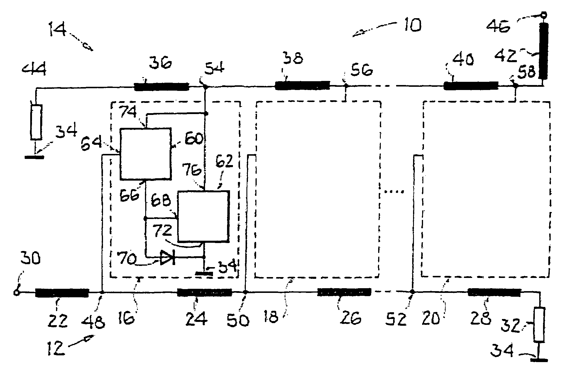
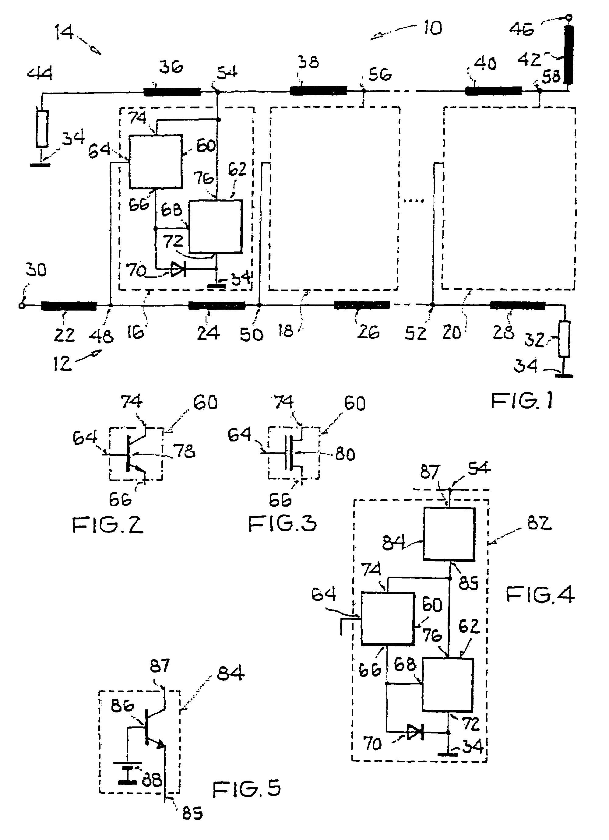
[0036]Specifically, FIG. 1 shows a distributed amplifier 10 with an input network 12, an output network 14, and n=3 unit cells 16, 18, 20, which are connected in parallel to one another between the input network 12 and the output network 14. The input network 12 has a series connection of inductive elements 22, 24, 26, 28, which connects an input 30 of the distributed amplifier 10 to a reference voltage 34 through an ohmic resistor 32. The output network 14 also has a series connection of inductive elements 36, 38, 40, 42, which connect a reference voltage connection 34 to an output 46 of the distributed amplifier 10 through an ohmic resistor 44.

[0037]Each unit cell 16, 18, 20 is connected to the input network 12 through one unit cell input 48, 50, 52 and is connected to the output network 14 through one unit cell output 54, 56, 58. Each pair of adjacent unit cell inputs 48, 50, 52 is connected together by one of the inductive elements 24, 26. In corresponding fashion, each pair of ...


PUM


Abstract

A distributed amplifier is provided that includes an input network that simulates an input signal transmission line, and having an output network that simulates an output signal transmission line, and also having multiple unit cells with amplifying characteristics that are connected in parallel to one another between the input network and the output network, that amplify a signal propagating through the input network and feed it into the output network with a predetermined phase relationship to a signal propagating through the output network. The distributed amplifier is characterized in that each unit cell has a multiplier with an input amplifier and an output amplifier, a control connection of the input amplifier is connected to the input network, a current connection of the input amplifier is connected to a control connection of the output amplifier and is connected through a diode to a current connection of the output amplifier, and current outputs of the input amplifier and of the output amplifier are connected to one another.

Description

[0001]This nonprovisional application claims priority under 35 U.S.C. § 119(a) on German Patent Application No. DE102005006717.4, which was filed in Germany on Feb. 4, 2005, and which is herein incorporated by reference.BACKGROUND OF THE INVENTION[0002]1. Field of the Invention[0003]The present invention relates to a distributed amplifier having an input network that simulates an input signal transmission line, and having an output network that simulates an output signal transmission line, and also having multiple unit cells with amplifying characteristics that are connected in parallel to one another between the input network and the output network, that amplify a signal propagating through the input network and feed it into the output network with a predetermined phase relationship to a signal propagating through the output network.[0004]2. Description of the Background Art[0005]Amplifier structures, which are known as “distributed amplifiers” or “traveling wave amplifiers,” are k...

Claims


Application Information

Patent Timeline
Patent Type & Authority Patents(United States)
IPC IPC(8): H03F3/60H03F3/68
CPCH03F3/58
Inventor JOODAKI, MOJTABA
Owner ATMEL CORP
Why Eureka
Try Eureka