Pressure compensation label for sticking to a surface, and method

a technology of pressure compensation and label, applied in the direction of identification means, electrical apparatus casings/cabinets/drawers, instruments, etc., can solve the problems of moisture and water not being able to penetrate the housing of the component, similar pressure compensation problems, and a large amount of materials, etc., to achieve simple and cost-effective manner, stable and mechanical resistan

Active Publication Date: 2019-06-04
SCHREINER GRP GMBH & CO KG
View PDF22 Cites 0 Cited by
  • Summary
  • Abstract
  • Description
  • Claims
  • Application Information

AI Technical Summary

Benefits of technology

[0017]In the case of the label described here, the second film lies directly on the first film, over a large area, laterally outside of the membrane. As a result of this large-area contact surface region, within which the first and the second film border on one another directly or are separated at most by an adhesive layer that lies between them, the pressure compensation label is particularly stable and mechanically resistant to external mechanical stresses, including pressure forces and shear forces. Furthermore, the label makes do with fewer films or other components, and can therefore be produced in particularly simple and cost-advantageous manner.
[0018]The ventilation channels ensure lateral offset of the respective outer opening in the label and the membrane top, in order to protect these from destruction by high-pressure washers or steam-jet degreasers, or from other stresses and / or contaminants. Depending on the embodiment, the ventilation channels of the first film can optionally lead to the outside at the outer edge of the first film or—if the outer channel end does not reach all the way to the film edge—can lead to the outside through channel exit openings of the second film.

Problems solved by technology

Similar problems of pressure compensation can occur, other than in automobile construction, also in other machines, industrial systems or devices.
Such pressure compensation openings do not remain exposed, but rather are covered in such a manner that pressure compensation by means of gas exchange continues to be possible, but wetness or moisture and water cannot penetrate into the housing of the component.
Such conditions of use have required a rather complex structure of pressure compensation labels until now, in which structure support structures between the foils / films can also be required in addition to foils / films and adhesive layers.

Method used


Image

  • Pressure compensation label for sticking to a surface, and method
  • Pressure compensation label for sticking to a surface, and method
  • Pressure compensation label for sticking to a surface, and method

Examples


Embodiment Construction

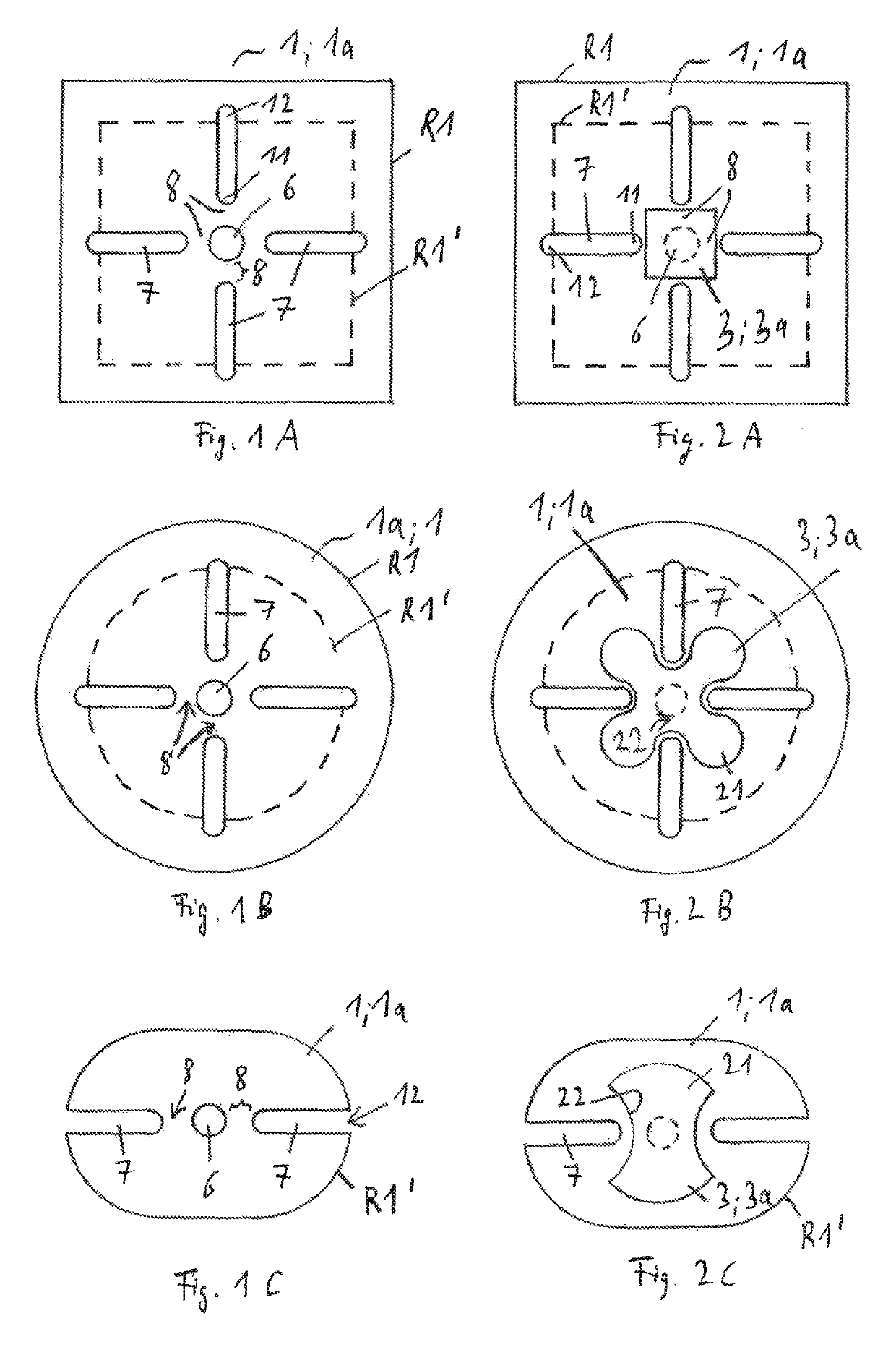
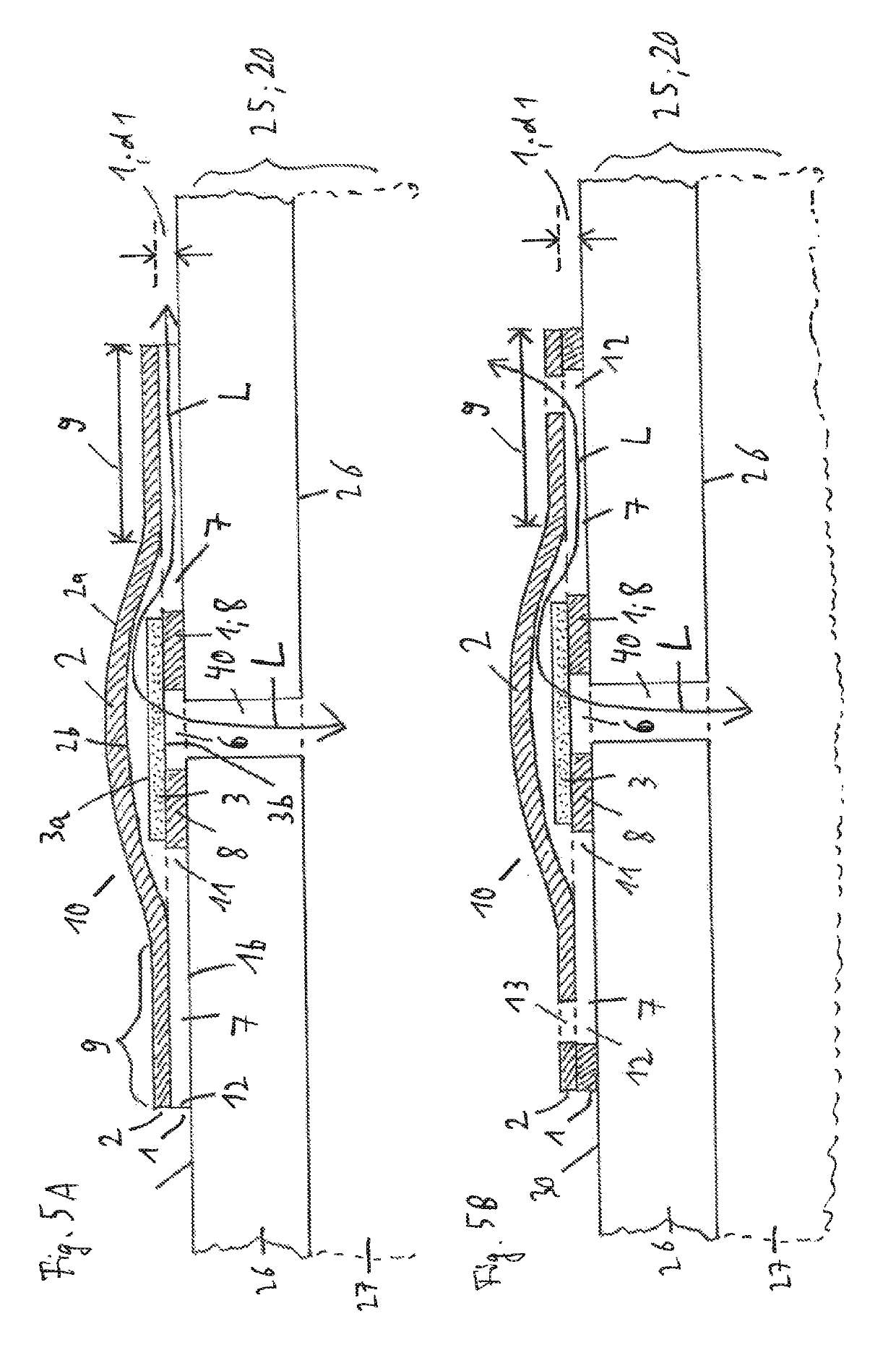
[0038]FIGS. 1A to 1C show some exemplary embodiment patterns for the lower (or inner, i.e. to be adhesively affixed directly to the surface of the device or housing) first film of the pressure compensation label. The views of the first film 1 shown in FIGS. 1A to 1C can be implemented, for example, as a cut pattern or punched pattern; in particular, a number of ventilation channels in the form of gaps or recesses can be configured outside of the central passage openings, above all as punched-out parts of the first film. The height of the ventilation channels then corresponds to the layer thickness d1 of the first film (cf. FIGS. 5A and 5B). However, the ventilation channels in the first film can alternatively be configured also as weakened film regions, particularly thinned in comparison with the remaining film thickness. In the simplest case, however, the first film is simply punched out in the region of the recess for the pressure compensation opening and also in the region of the...


PUM

PropertyMeasurementUnit
pressureaaaaaaaaaa
distanceaaaaaaaaaa
air-permeableaaaaaaaaaa

Abstract

A pressure compensation label for sticking to a surface, provided with a pressure compensation opening, of a housing or some other article, has a first film for sticking to a surface provided with a pressure compensation opening, and an outer, second film and also an air-permeable membrane film which is arranged between the first film and the second film. The first film has a cutout, intended for positioning over a pressure compensation opening, and a number of ventilation ducts. Each of the ventilation ducts is separated from the cutout by a film region of the first film. The membrane film covers the cutout and each of the film regions between the cutout and the number of ventilation ducts. The outer, second film extends laterally beyond the membrane film, at least regionally covers the number of ventilation ducts of the first film laterally outside the membrane film, and spans a ventilation path which leads from that surface of the membrane film that faces the second film to the number of ventilation ducts in the first film.

Description

CROSS REFERENCE TO RELATED APPLICATIONS[0001]This application is the National Stage of PCT / EP2015 / 057749 filed on Apr. 9, 2015, which claims priority under 35 U.S.C. § 119 of German Application No. 10 2014 105 193.9 filed on Apr. 11, 2014, the disclosure of which is incorporated by reference. The international application under PCT article 21(2) was not published in English.BACKGROUND OF THE INVENTION1. Field of the Invention[0002]The application relates to a pressure compensation label for adhesive affixation to a surface of a housing or another article, which surface is provided with a pressure compensation opening. The application furthermore relates to a method for the production of pressure compensation labels.2. Description of the Related Art[0003]The most varied systems, devices, components or individual parts in mechanical engineering, in automotive construction or in other areas of application possess pressure compensation openings. Housings or outer housings, above all, ar...

Claims


Application Information

Patent Timeline
Patent Type & Authority Patents(United States)
IPC IPC(8): B32B37/22G09F3/02G09F3/10B32B3/26B32B3/30H05K5/06H05K5/02B32B38/10B32B38/04B65D77/22B65D25/20B01D63/08B32B37/02B32B5/02
CPCG09F3/02B32B3/266B32B3/30B32B5/022B32B5/024B32B37/02B32B37/22B32B38/04B32B38/10B65D25/205B65D77/225G09F3/10H05K5/0213H05K5/068B01D63/087G09F2003/0272B32B2038/042B32B2305/188B32B2305/20B32B2307/724B32B2307/7265B32B2519/00B65D2203/02B65D2205/00G09F2003/0233G09F2003/0236H05K5/0215
Inventor BIRK, UWE
Owner SCHREINER GRP GMBH & CO KG
Why Eureka
Try Eureka