System and method for cross table tomosynthesis imaging for trauma applications

a tomosynthesis and trauma application technology, applied in the field of tomosynthesis imaging, can solve the problems of not being able to differentiate between overlapping bony structures, unable to provide views through thick parts of the patient anatomy (for example, the shoulder), and the system may not localize the site of the injury in three dimensions

Active Publication Date: 2008-08-26
GENERAL ELECTRIC CO
View PDF11 Cites 17 Cited by
  • Summary
  • Abstract
  • Description
  • Claims
  • Application Information

AI Technical Summary

Problems solved by technology

Additionally, tomosynthesis is relatively fast and cost-effective.
However, such systems often fail to provide views through thick parts of a patient anatomy (for example, a shoulder) or to differentiate between overlapping bony structures (for example, a skull).
In addition, such systems may not localize the site of the injury in three dimensions.
First, these systems are not typically found in emergency rooms.
Therefore, additional time is required to move a patient to a CT system.
In addition, CT scanning is usually slow compared to x-ray imaging.
In emergency situations, this additional time may not be available.

Method used


Image

  • System and method for cross table tomosynthesis imaging for trauma applications
  • System and method for cross table tomosynthesis imaging for trauma applications
  • System and method for cross table tomosynthesis imaging for trauma applications

Examples


Embodiment Construction

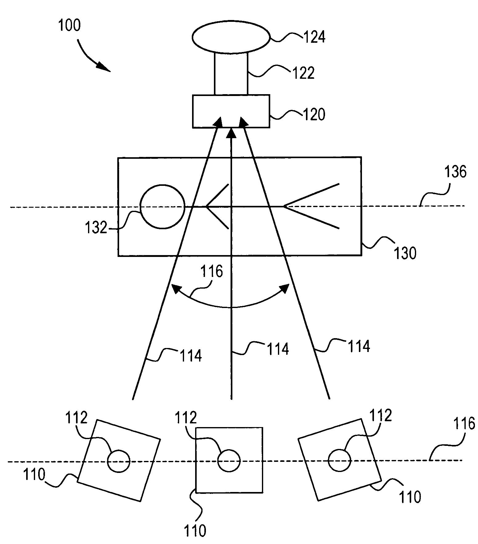
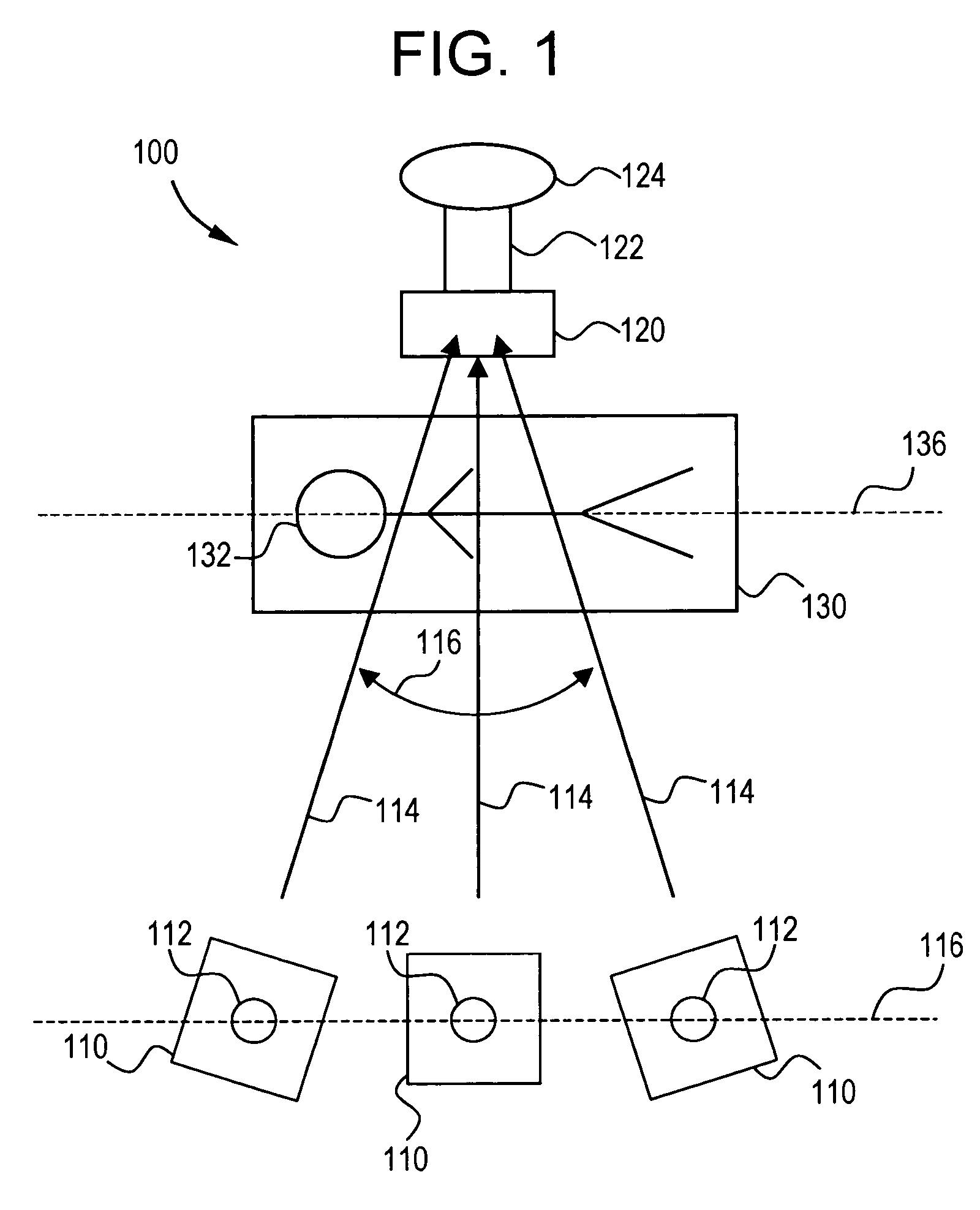
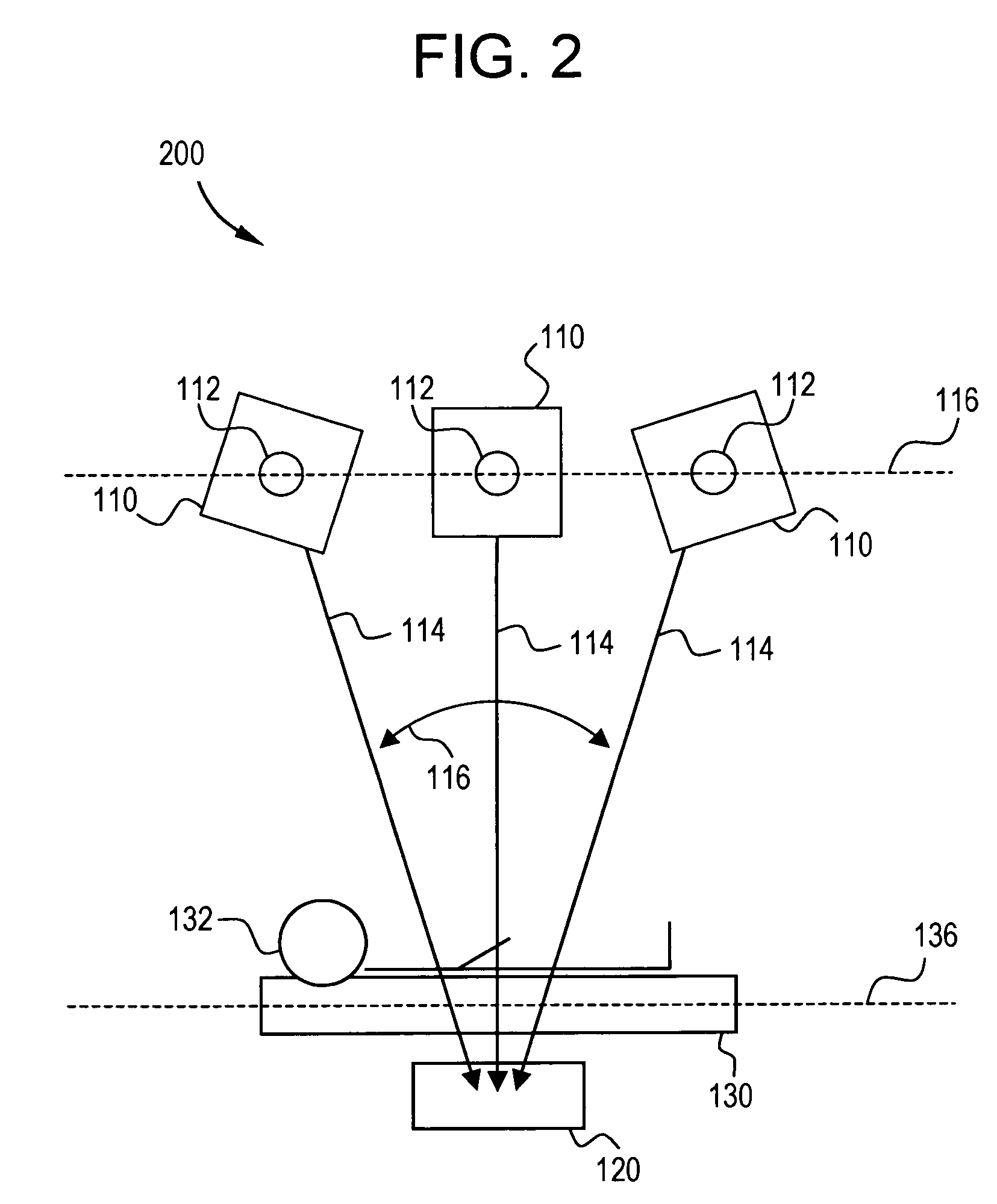
[0018]FIG. 1 illustrates a schematic diagram of a tomosynthesis imaging system 100 demonstrating an x-ray imaging device 110 in three example positions in accordance with an embodiment of the presently described technology. System 100 includes an x-ray imaging device 110 (illustrated in three example positions, herein referred to as a left, center, and right positions), an x-ray detector 120, and a patient surface 130.

[0019]X-ray imaging device 110 includes any device capable of emitting x-rays 114 useful for imaging a patient 132 or patient anatomy from a plurality of positions. For example, device 110 can include an x-ray tube. Imaging device 110 can also include a point of reference 112. Point of reference 112 can be useful in describing one or more paths of motion or trajectories that imaging device 110 may move relative to detector 120 and / or patient surface 130.

[0020]X-ray imaging device 110 may include a collimator (not shown). The collimator is configured to adjust a field o...


PUM


Abstract

The presently described technology provides a tomosynthesis imaging system that comprises an x-ray tube and an anti-scatter grid. The x-ray tube is configured to emit x-rays from a plurality of positions during movement of the x-ray tube along a long axis of a mobile patient surface. The anti-scatter grid is configured to filter out scattered x-rays and includes a grid line parallel to the long axis of the mobile patient surface. The x-rays emitted from the plurality of positions are reconstructed into at least one image of at least one plane of a patient anatomy. The described technology is useful in emergency or trauma applications where a patient may be quickly and easily moved on a mobile patient surface to a position near an x-ray detector used in combination with the x-ray tube and anti-scatter grid.

Description

RELATED APPLICATIONS[0001]Not Applicable.FEDERALLY SPONSORED RESEARCH OR DEVELOPMENT[0002]Not Applicable.BACKGROUND OF THE INVENTION[0003]The present invention relates generally to tomosynthesis imaging. More specifically, the invention relates to cross table tomosynthesis in a trauma application.[0004]Tomography involves obtaining a two-dimensional image slice (or tomogram) from a three-dimensional volume. A variety of tomographic imaging techniques exist today, such as conventional linear tomography, computed axial tomography (CT), and positron emission tomography (PET).[0005]A relatively new and promising tomographic imaging technique is tomosynthesis. Tomosynthesis allows retrospective reconstruction of an arbitrary number of tomographic planes of anatomies from a set of projection images acquired over a variety of angles. Compared to conventional linear tomography, tomosynthesis provides premium image quality and enhanced depth information at a lower x-ray dose. Image quality a...

Claims


Application Information

Patent Timeline
Patent Type & Authority Patents(United States)
IPC IPC(8): A61B6/00
CPCA61B6/025G01N23/046G01N2223/612G01N2223/419A61B6/4291G01N23/044
Inventor LI, BAOJUNUPPALURI, RENUKATHOMAS, CARSON HALESCHULTE, GERALD PAULAVINASH, GOPAL B.SAUNDERS, ROWLAND F.MERISOTIS, TAMMY M.
Owner GENERAL ELECTRIC CO
Why Eureka
Try Eureka