Eureka AIR delivers breakthrough ideas for toughest innovation challenges, trusted by R&D personnel around the world.

Sanding block

Inactive Publication Date: 2008-09-02
J R REEVES
View PDF28 Cites 8 Cited by
  • Summary
  • Abstract
  • Description
  • Claims
  • Application Information

AI Technical Summary

Benefits of technology

[0005]A primary object of the invention is to provide a sanding block comprising slideably interrelated parts for accommodating an endless sanding belt and having dual action means for selectively moving the parts into bearing relation with the sanding belt for maintaining tension thereon or moving the parts out of such bearing relation with the sanding belt for facilitating removal or adjustment of the sanding belt relative to the sanding block.

Problems solved by technology

However, most are limited in that release of that tension for removal of the sanding belt from the sanding block can be obtained only by manual compression together of the parts by the hands or fingers of the user.
In addition, while the sanding blocks of the prior art have flat lower and upper faces and small, curved or pointed ends for sanding flat and small curved or hard to reach surfaces, they lack a curved face for sanding larger curved surfaces.

Method used


Image

  • Sanding block
  • Sanding block
  • Sanding block

Examples


Embodiment Construction

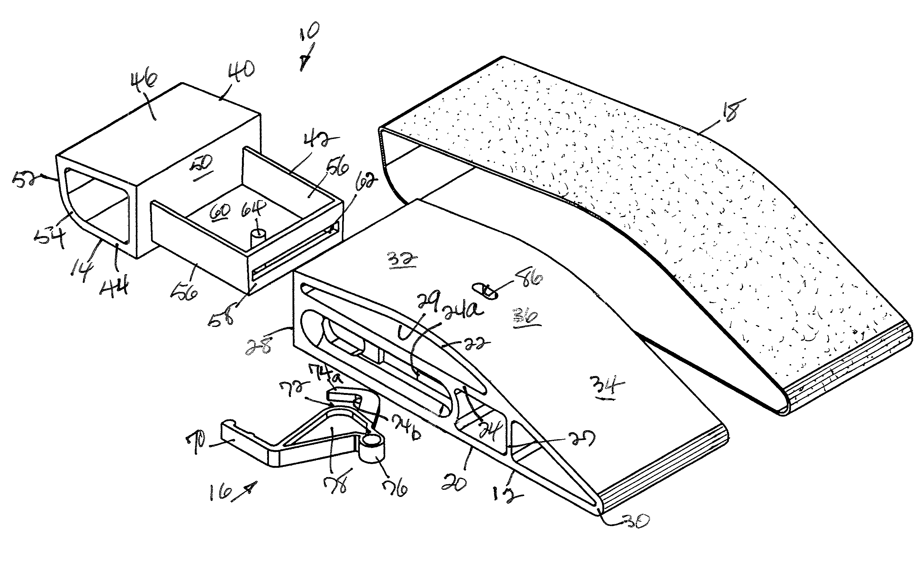
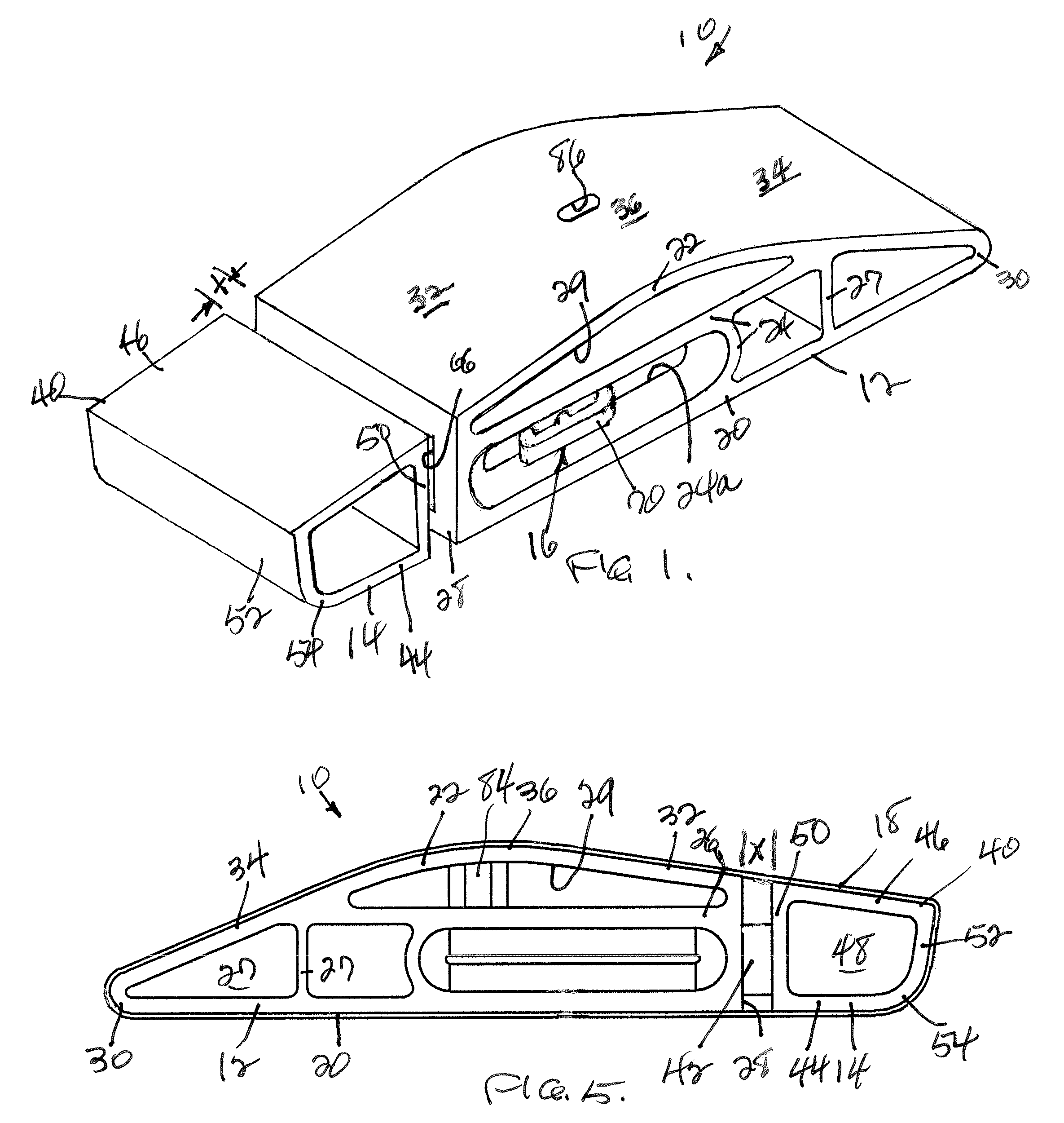
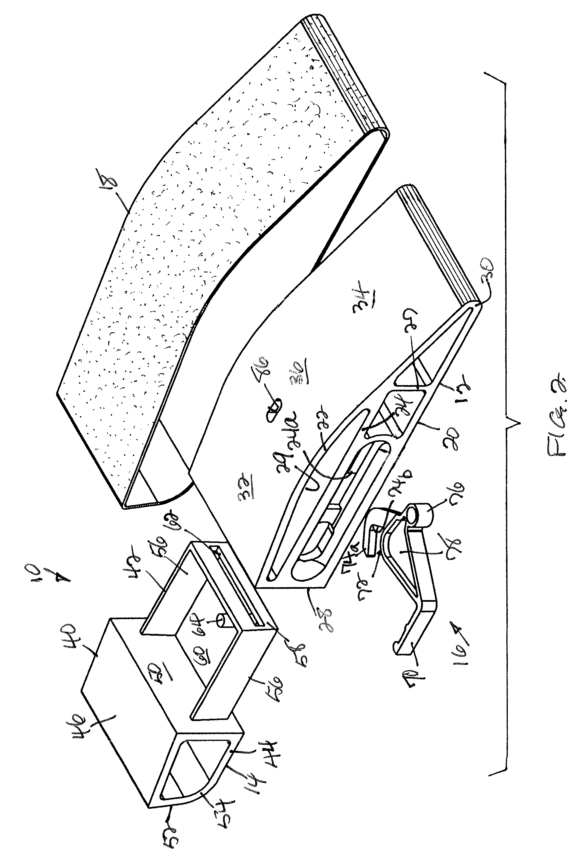
[0017]The sanding block of the invention, which may be easily gripped by hand, is generally indicated by 10 and includes coaxially aligned, substantially rectangular, slideably interrelated main and secondary parts, 12 and 14 respectively, and dual action means, generally indicated by 16, all fabricated from any suitable strong, lightweight material, with the dual action means being mounted for pivotal movement within the main part 12 for effecting sliding longitudinal movement of the secondary part in opposite directions toward or away from the main part thereby adjusting the spacing between the main and secondary parts, as will appear.

[0018]An endless sanding belt 18 is provided and has appropriate contours to extend longitudinally around sanding block 10 in sleeving manner, with actuation of the dual action means effecting sliding movement of the sanding block secondary part between fully extended and fully retracted positions relative to the main part for varying the tension exe...


PUM


Abstract

A sanding block comprising slideably interrelated parts for accommodating an endless sanding belt and having a dual action means for selectively moving the parts into bearing relation with the sanding belt for maintaining tension thereon or moving the parts out of such bearing relation with the sanding belt for facilitating removal or adjustment of the sanding belt relative to the sanding block, while also providing the sanding block with a novel convexly curved surface for improved tool versatility.

Description

FIELD OF THE INVENTION[0001]The present invention relates to a sanding block comprising slideably interrelated sections or parts for accommodating an endless sanding belt and provided with means for adjusting the tension exerted by the sanding block on the sanding belt.BACKGROUND OF THE INVENTION[0002]A wide variety of sanding blocks comprising sections or parts for accommodating an endless sanding belt are shown in the prior art, with virtually all utilizing resilient means for holding the parts in spaced relation for maintaining tension on the sanding belt. However, most are limited in that release of that tension for removal of the sanding belt from the sanding block can be obtained only by manual compression together of the parts by the hands or fingers of the user.[0003]In addition, while the sanding blocks of the prior art have flat lower and upper faces and small, curved or pointed ends for sanding flat and small curved or hard to reach surfaces, they lack a curved face for s...

Claims


Application Information

Patent Timeline
IPC IPC(8): B24D15/00
CPCB24D15/023B24B21/20
Inventor REEVES, SR., JAMES R.
Owner J R REEVES
Why Eureka
Eureka Blog
Learn More