Structure of canopy

a technology of structure and canopy, applied in tents/canopies, building types, constructions, etc., can solve the problems of weak structure, difficult water drainage, and aesthetics of appearan

Inactive Publication Date: 2008-09-09
KIM DAE HWAN
View PDF17 Cites 55 Cited by
  • Summary
  • Abstract
  • Description
  • Claims
  • Application Information

AI Technical Summary

Benefits of technology

[0007]To solve the above and other problems, the present invention provides the structure of a canopy in a variety of shapes, by which the inner side surface and the center of the top end of a roof is made pointed without an additional vertical rod by using a difference in the length of rods. The structure of a canopy can be applied to a pyramid type roof, a slate (gable) type roof, a cross type roof, a cross-pyramid type roof, and a modified cross-pyramid type roof according to various shape and type of roofs. Thus, smooth drainage and aesthetic appearance are possible. Also, by reinforcing the edge of a roof, smooth drainage is possible and the canopy is strong to an external force.
[0008]Also, the present invention provides the structure of a canopy by which a roof can be extended in multiple units of roofs and a user can conveniently use a key lever. Also, by forming a ventilating opening and a sunshield roof on the roof, air circulation inside the canopy is made smooth and temperature can be controlled. Further, products can be made luxury.
[0011]A corner facing the center of the roof is formed in a pyramid shape to improve outer appearance of the canopy and endure an outside force. To reinforce a corner formed to face the center of the roof, a corner reinforcement bar capable of being hinge coupled between the roof end connection block and the upper head connection block.

Problems solved by technology

Thus, the appearance is not aesthetic.
Also, since the line of the edge of a roof is not distinctive, the roof cloth sags so that water drainage is not easy and the entire structure is weak.
Also, using the roof by extending it is difficult.
When a user manipulates a snap button, a finger of the user may be damaged.
Since ventilation of a roof is not smooth, air does not circulate well inside.
Also, producing luxury products is difficult.

Method used


Image

  • Structure of canopy
  • Structure of canopy
  • Structure of canopy

Examples


Embodiment Construction

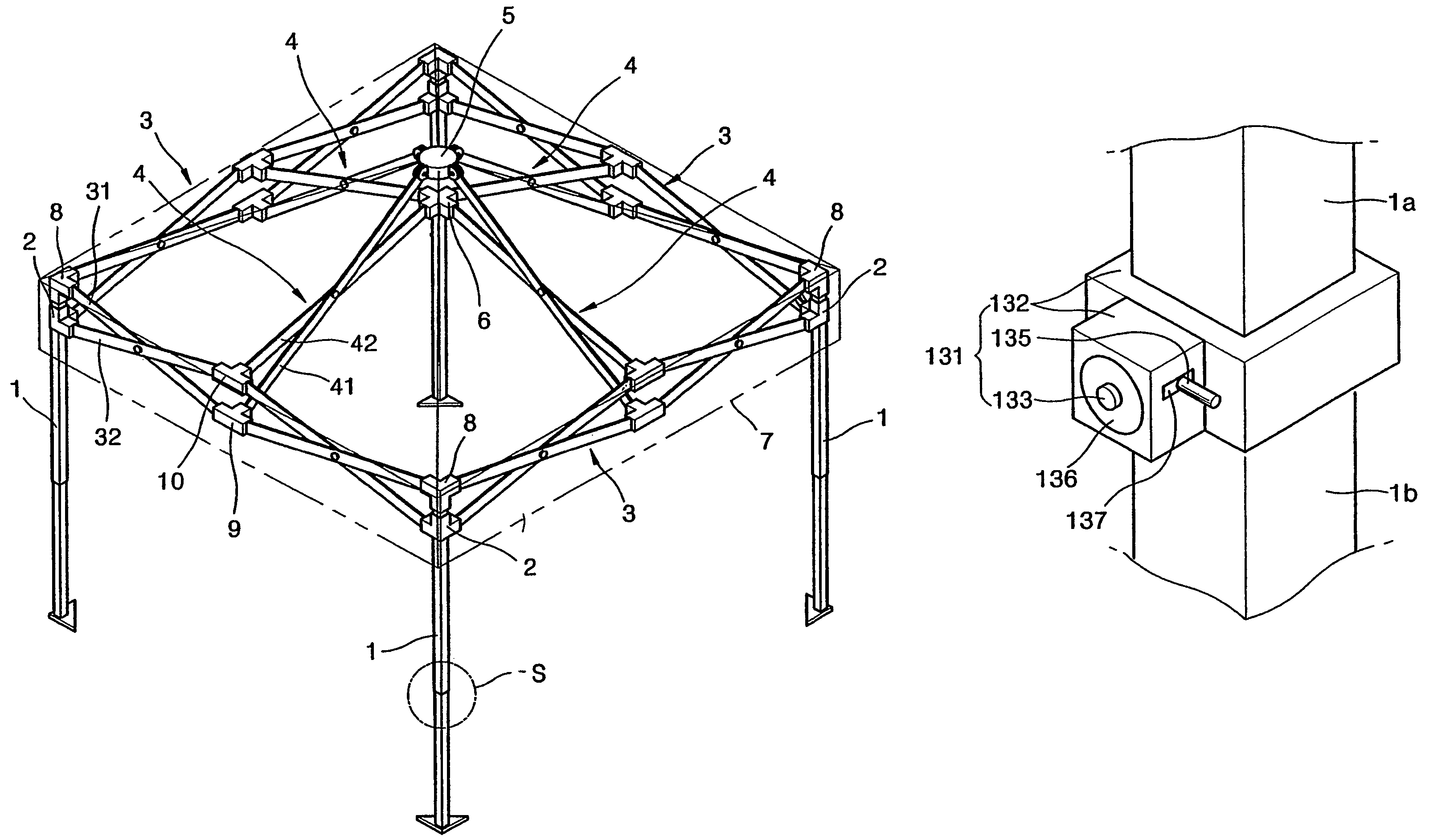
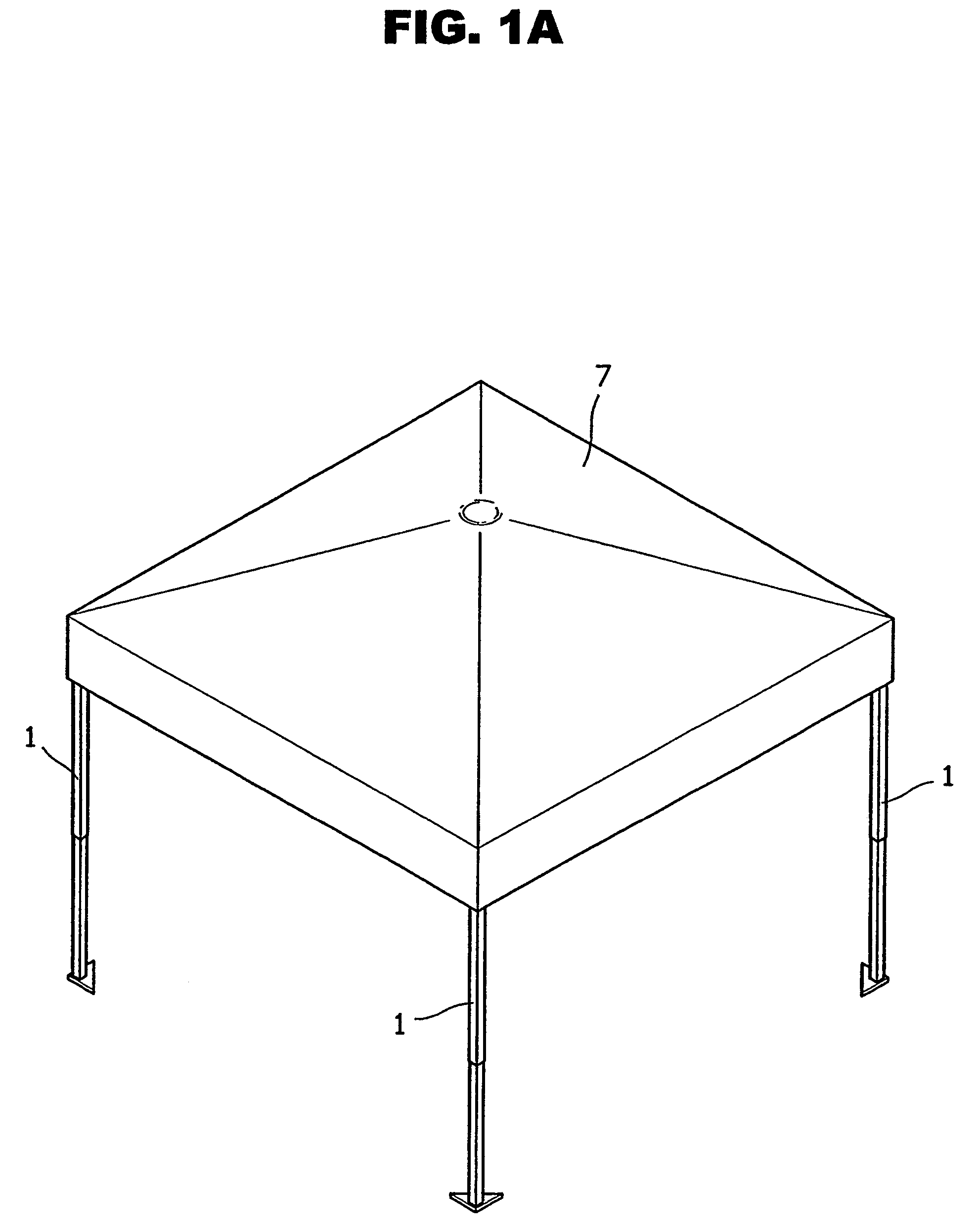
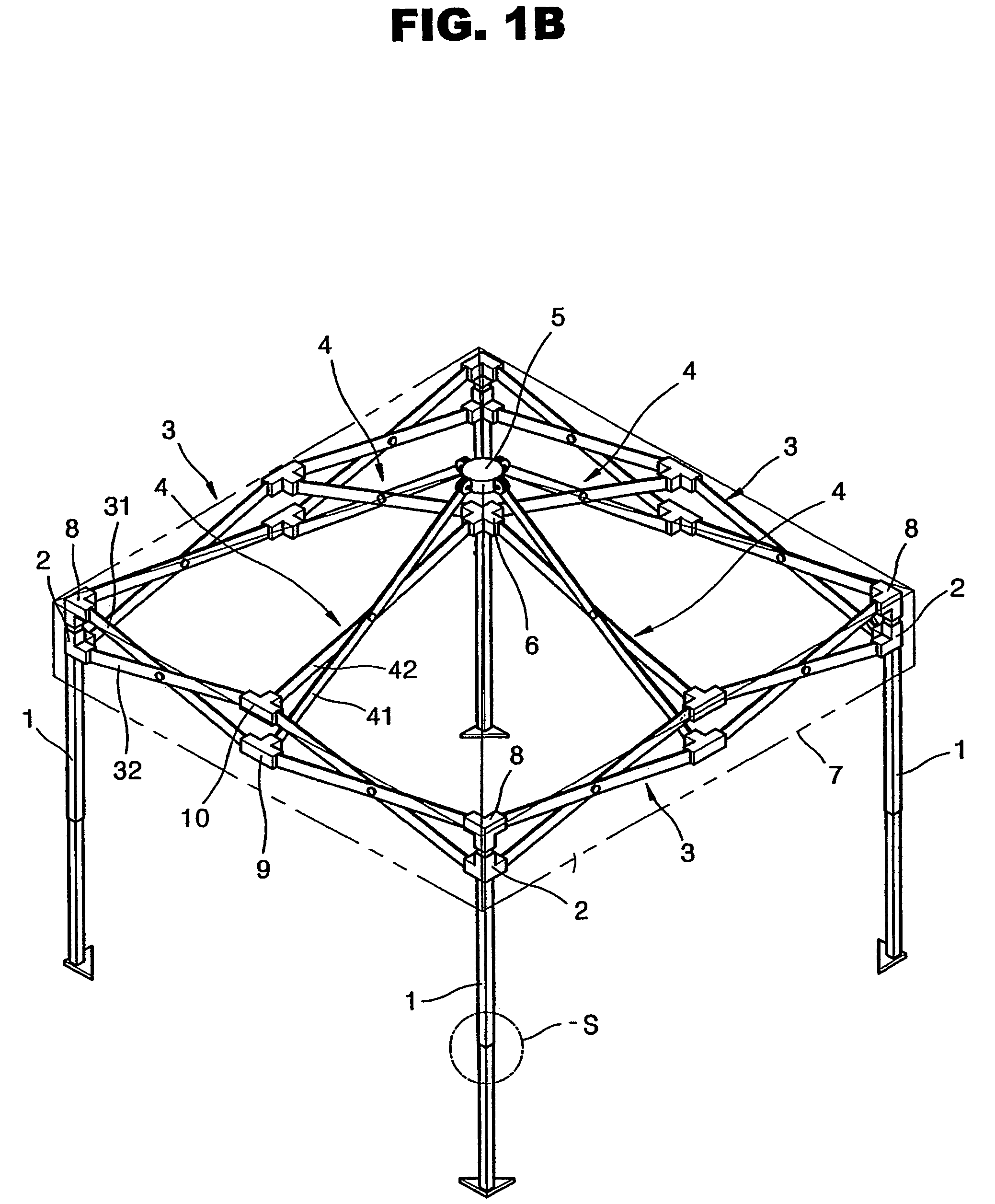
[0039]Referring to FIGS. 1A and 1B, the structure of a canopy according to a preferred embodiment of the present invention includes a pillar 1, a slide connection block 2, an end portion connection block 8, a roof edge frame 3, a roof center frame 4, a rod connection block 10, an upper head connection block 5, a lower head connection block 6, and a roof cloth 7.

[0040]The pillar 1 is erected from the ground to support the canopy of the present invention. The pillar 1 is vertically erected in a multiple number to support a roof such that four pillars are installed for a single unit canopy as shown in FIG. 1B, minimum six pillars are installed for a double unit canopy as shown in FIG. 2A, and minimum eight pillars are installed for a three-unit canopy. Also, as shown in FIGS. 2B and 2C, for a four-unit canopy arranged in a square form, peripheral pillars are installed so that a total of eight pillars are installed while a center pillar is removed.

[0041]As shown in FIGS. 2B and 2C, the ...


PUM


Abstract

A structure of a canopy includes a plurality of pillars, an end portion connection block fixed to an end portion of the pillar, a slide connection block capable of sliding along the pillar, a plurality of roof edge frames, a plurality of roof center frames, a rod connection block connecting the roof edge frame and the roof center frame, an upper head connection block pivoting with respect to the first rod of each of the roof center frames to form an outer top end of the roof, a lower head connection block pivoting with respect to the second rod of each of the roof center frames to form an inner top end of the roof, a connection block including a corner reinforcement bar capable of being hinge coupled between the roof end connection block and the upper head connection block to reinforce a corner formed to face the center of the roof, and a roof cloth covering the roof edge frame and the roof center frame.

Description

BACKGROUND OF THE INVENTION[0001]1. Field of the Invention[0002]The present invention relates to the structure of a canopy, and more particularly, to the structure of a canopy which is firm, has an aesthetic appearance, and is used in various ways.[0003]2. Description of the Related Art[0004]In general, a simple sun shield or a simple house, that is, a canopy, in which a frame is set up to a predetermined height and a roof is covered over the frame to shield wind or sunshine outdoors, is widely used in camping areas, street events, or athletic meetings. The canopy is built by setting up pillars, connecting roof edge frames and roof center frames in a hinge type by using a plurality of connection blocks, covering the frames with roof cloth.[0005]However, since the roof edge frames and the roof center frames are made of rods having the same length in an X structure, the appearance of the roof is flat, or a simple conic shape by installing a vertical rod at the center of the roof. Thus...

Claims


Application Information

Patent Timeline
Patent Type & Authority Patents(United States)
IPC IPC(8): E04H15/50
CPCE04H15/50
Inventor KIM, DAE HWAN
Owner KIM DAE HWAN
Why Eureka
Try Eureka