Tire inflation pressure sensing apparatus with function of detecting tire location

a technology of pressure sensing apparatus and tire location, which is applied in vehicle tyre testing, instruments, roads, etc., can solve the problems of inability of the receiver to determine whether a signal is received, the receiver cannot determine the location of each of the transmitters (i.e., each of the tires) in the vehicle, and the receiver cannot determine from which one of the transmitters a pressure signal received thereby has been sent, so as to save time-consuming and additional devices

Active Publication Date: 2008-09-16
DENSO CORP
View PDF8 Cites 18 Cited by
  • Summary
  • Abstract
  • Description
  • Claims
  • Application Information

AI Technical Summary

Benefits of technology

[0017]It is, therefore, a primary object of the present invention to provide a tire inflation pressure sensing apparatus which is configured to sense inflation pressures of tires of a vehicle and can reliably detect the location of each of the tires in the vehicle without registration of reference ID signals in a receiver thereof.
[0054]Accordingly, the tire inflation pressure sensing apparatus according to the present invention can reliably detect the location of each of the transmitters (i.e., the location of each of the tires of the vehicle) without registering reference ID signals in the receiver, thus saving the time-consuming task and additional devices required for the registration of reference ID signals in the receiver 3.

Problems solved by technology

However, it is impossible for the receiver to determine whether a signal received thereby has been sent out from one of the transmitters or from a signal source located outside the vehicle.
Moreover, it is impossible for the receiver to detect the location of each of the transmitters (i.e., each of the tires) in the vehicle.
In other words, the receiver cannot determine from which one of the transmitters a pressure signal received thereby has been sent out.
However, the registration of reference ID signals in the receiver is a time-consuming task and necessitates some additional devices.

Method used


Image

  • Tire inflation pressure sensing apparatus with function of detecting tire location
  • Tire inflation pressure sensing apparatus with function of detecting tire location
  • Tire inflation pressure sensing apparatus with function of detecting tire location

Examples


first embodiment

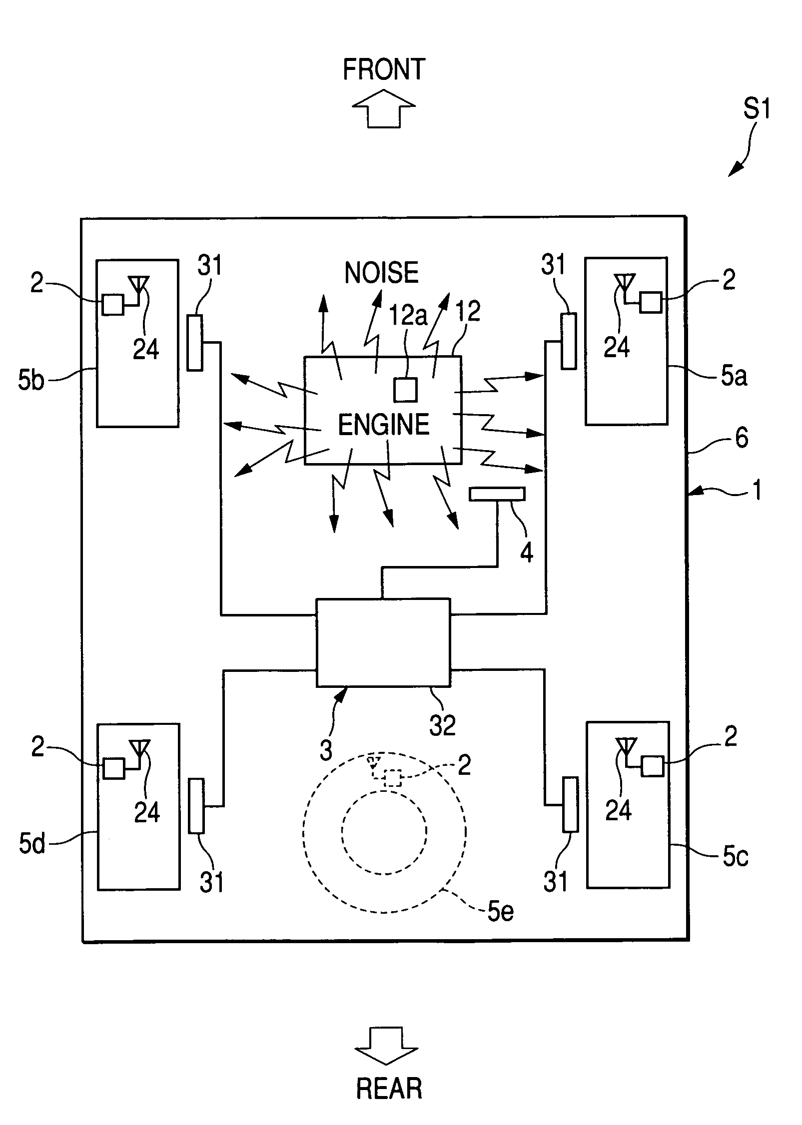
[0081]FIG. 1 shows the overall configuration of a tire inflation pressure sensing apparatus S1 according the first embodiment of the invention.

[0082]The tire inflation pressure sensing apparatus S1 is installed to a vehicle 1; it is configured to sense inflation pressures of four tires each of which is mounted on one of four wheels 5a-5d of the vehicle 1 (i.e., the front-right wheel 5a, the front-left wheel 5b, the rear-right wheel 5c, and the rear-left wheel 5d).

[0083]As shown in FIG. 1, the tire inflation pressure sensing apparatus S1 includes four transmitters 2, each of which is installed to one of the four wheels 5a-5d, a receiver 3 installed to the body 6 of the vehicle 1, and a warning device 4 electrically connected to the receiver 3.

[0084]Each transmitter 2 is configured to sense an inflation pressure of a corresponding one of the four tires and send out a frame that contains a signal representative of the sensed inflation pressure of the tire.

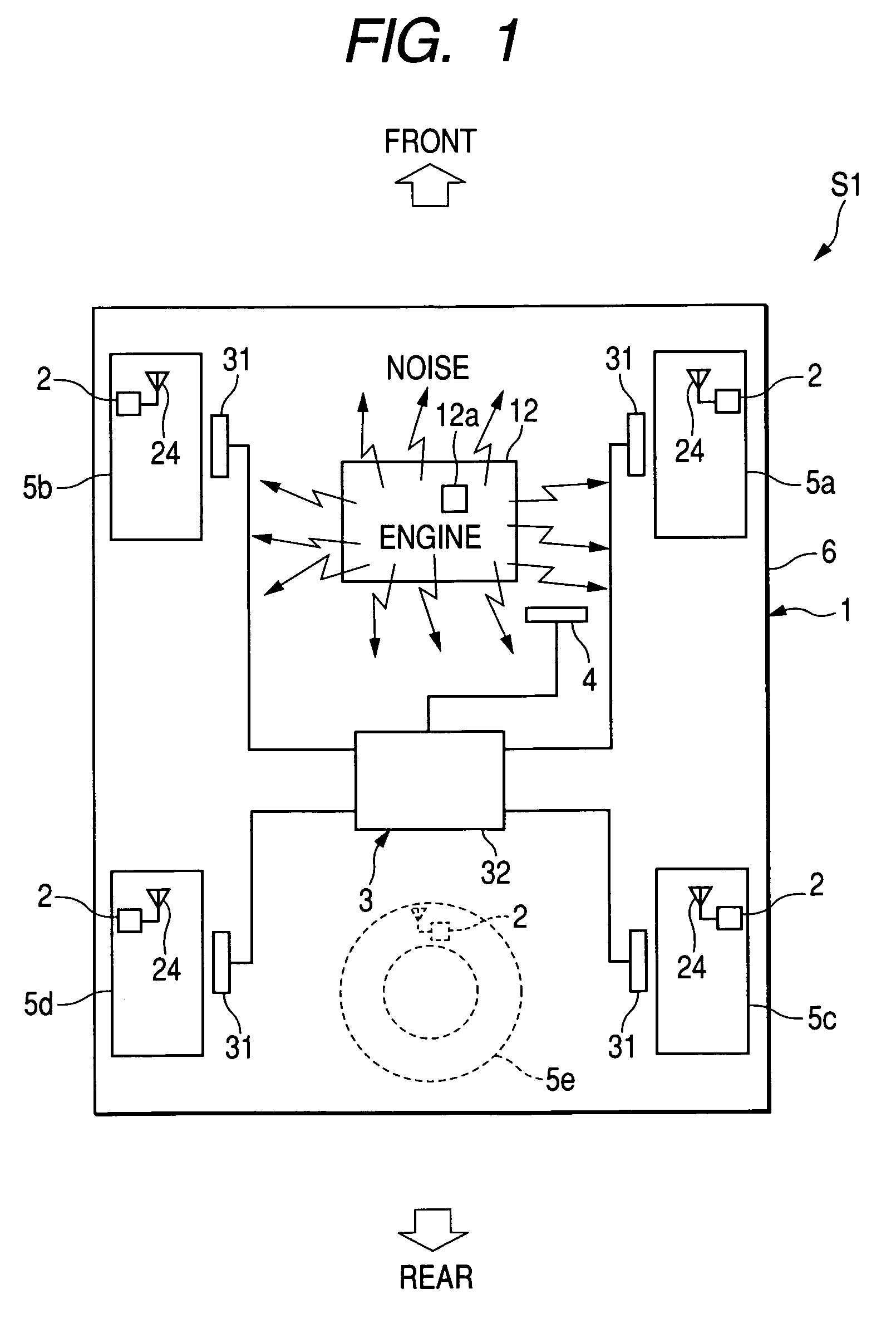
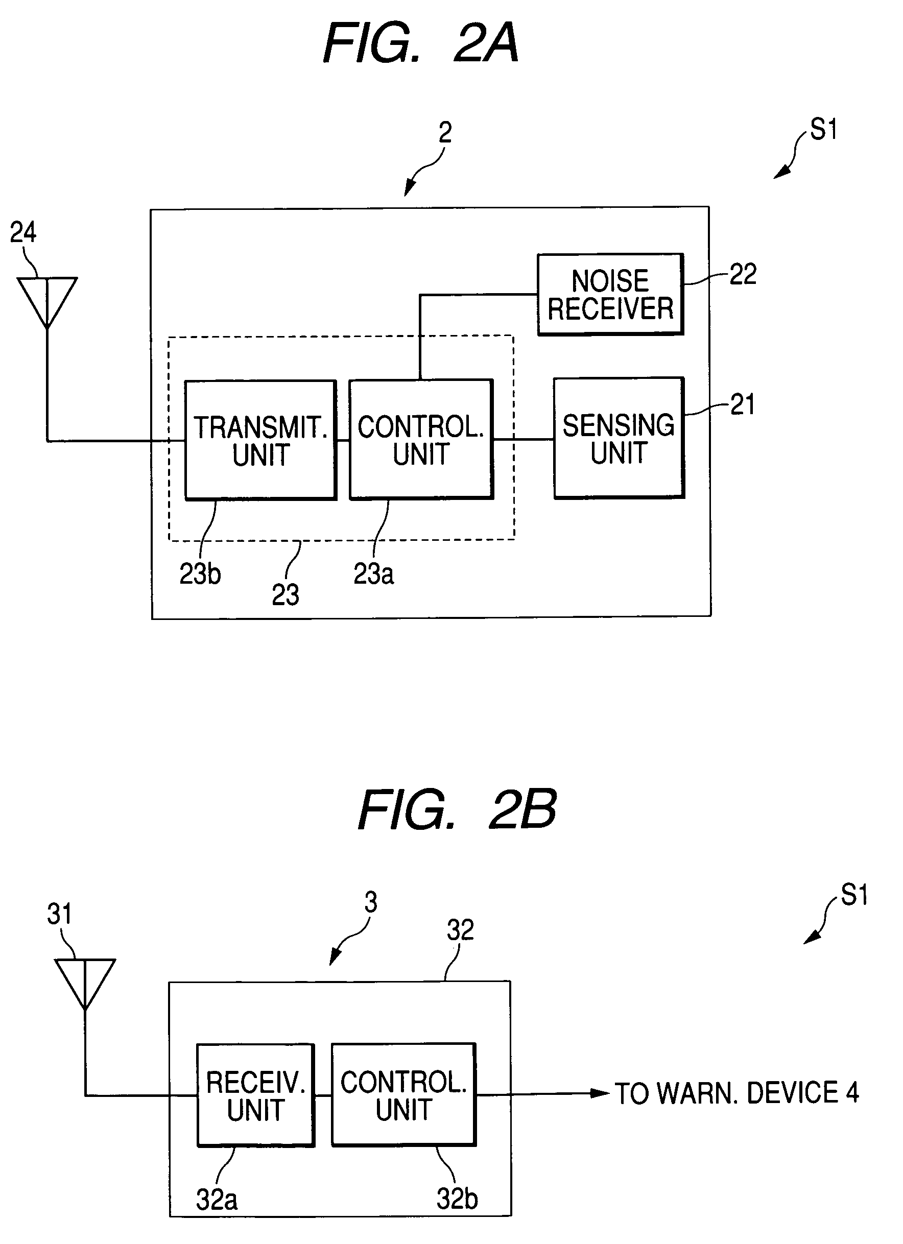
[0085]Referring to FIG. 2A, ea...

second embodiment

[0118]In this embodiment, a tire inflation pressure sensing apparatus S2 is provided which has a configuration almost identical to that of the inflation pressure sensing apparatus S1 according to the previous embodiment. Accordingly, only the difference in configuration between the tire inflation pressure sensing apparatuses S1 and S2 is to be described below.

[0119]As described previously, in the tire inflation pressure sensing apparatus S1, each of the transmitters 2 is configured to determine whether a corresponding one of the four wheels (i.e., the wheel to which the transmitter 2 is installed) is a front-wheel or a rear-wheel of the vehicle 1 based on a level of the noise received by the noise receiver 22 thereof and send out a frame containing a location signal representative of the determination results. On the other hand, the receiver 3 is configured to receive each of the frames sent out from the transmitters 2 and identify whether a corresponding one of the transmitters 2 (...

third embodiment

[0124]In this embodiment, a tire inflation pressure sensing apparatus S3 is provided which has a configuration almost identical to that of the inflation pressure sensing apparatus S1 according to the first embodiment. Accordingly, only the difference in configuration between the tire inflation pressure sensing apparatuses S1 and S3 is to be described below.

[0125]In the tire inflation pressure sensing apparatus S1 according to the first embodiment, a noise generated by a noise source located in the vehicle 1 is utilized to make a determination for each of the transmitters 2 as to whether the transmitter 2 is installed to a front-wheel or a rear-wheel of the vehicle 1.

[0126]In comparison, in the tire inflation pressure sensing apparatus S3, an acceleration signal generated by an acceleration sensor (to be referred to as G sensor hereinafter) of each of the transmitters 2 is used to determine whether the transmitter 2 is installed to a right-wheel of a left-wheel of the vehicle 1.

[0127...


PUM

PropertyMeasurementUnit
frequencyaaaaaaaaaa
pressureaaaaaaaaaa
circumferential accelerationaaaaaaaaaa

Abstract

A tire inflation pressure sensing apparatus according to the invention includes a plurality of transmitters, each of which is provided on one of a plurality of wheels of a vehicle, and a receiver provided on a body of the vehicle. Each transmitter includes a pressure sensor working to generate a pressure signal representative of an inflation pressure of a tire on a corresponding one of the wheels and a noise receiver working to receive a noise generated by a noise source in the vehicle. Each transmitter is configured to transmit the pressure signal and the received noise to the receiver. The receiver is configured to determine the inflation pressures of tires based on the pressure signals and make a determination for each of the transmitters as to whether the transmitter is provided on a front-wheel or a rear-wheel of the vehicle based on a level of the corresponding received noise.

Description

CROSS-REFERENCE TO RELATED APPLICATION[0001]This application claims priority from Japanese Patent Applications No. 2004-250504, filed on Aug. 30, 2004, and No. 2004-143400, filed on May 13, 2004, the contents of which are hereby incorporated by reference into this application.BACKGROUND OF THE INVENTION[0002]1 Technical Field of the Invention[0003]The present invention relates generally to tire inflation pressure sensing apparatuses or sensors. More particularly, the invention relates to a direct-type tire inflation pressure sensing apparatus which is configured to sense inflation pressures of tires of a vehicle and has a function of detecting the location of each of the tires in the vehicle.[0004]2 Description of the Related Art[0005]Conventional direct-type tire inflation pressure sensing apparatuses generally include a plurality of transmitters and a receiver.[0006]Each of the transmitters is directly installed to one of a plurality of wheels of a vehicle and includes a pressure ...

Claims


Application Information

Patent Timeline
Patent Type & Authority Patents(United States)
IPC IPC(8): B60C23/00B60C23/02G01L17/00B60C23/04B60C23/20G08C17/02
CPCB60C23/0466B60C23/0416
Inventor MORI, MASASHIWATABE, NOBUYAOKUMURA, RYOUZOU
Owner DENSO CORP
Why Eureka
Try Eureka