Dual compression pad for surgical positioner units

Active Publication Date: 2008-09-23
INNOVATIVE MEDICAL PRODS
View PDF5 Cites 41 Cited by
  • Summary
  • Abstract
  • Description
  • Claims
  • Application Information

AI Technical Summary

Benefits of technology

[0006]A dual compression foam pad arrangement for use with surgical postioner devices is formed from a single pair of foam pieces that are cloverleaf-shaped to provide more flexible contact with the patient. The foam piece in contact with the patient is made of a more po

Problems solved by technology

Since the pads are held together by cement, the cement could possibly become p

Method used


Image

  • Dual compression pad for surgical positioner units
  • Dual compression pad for surgical positioner units
  • Dual compression pad for surgical positioner units

Examples


Embodiment Construction

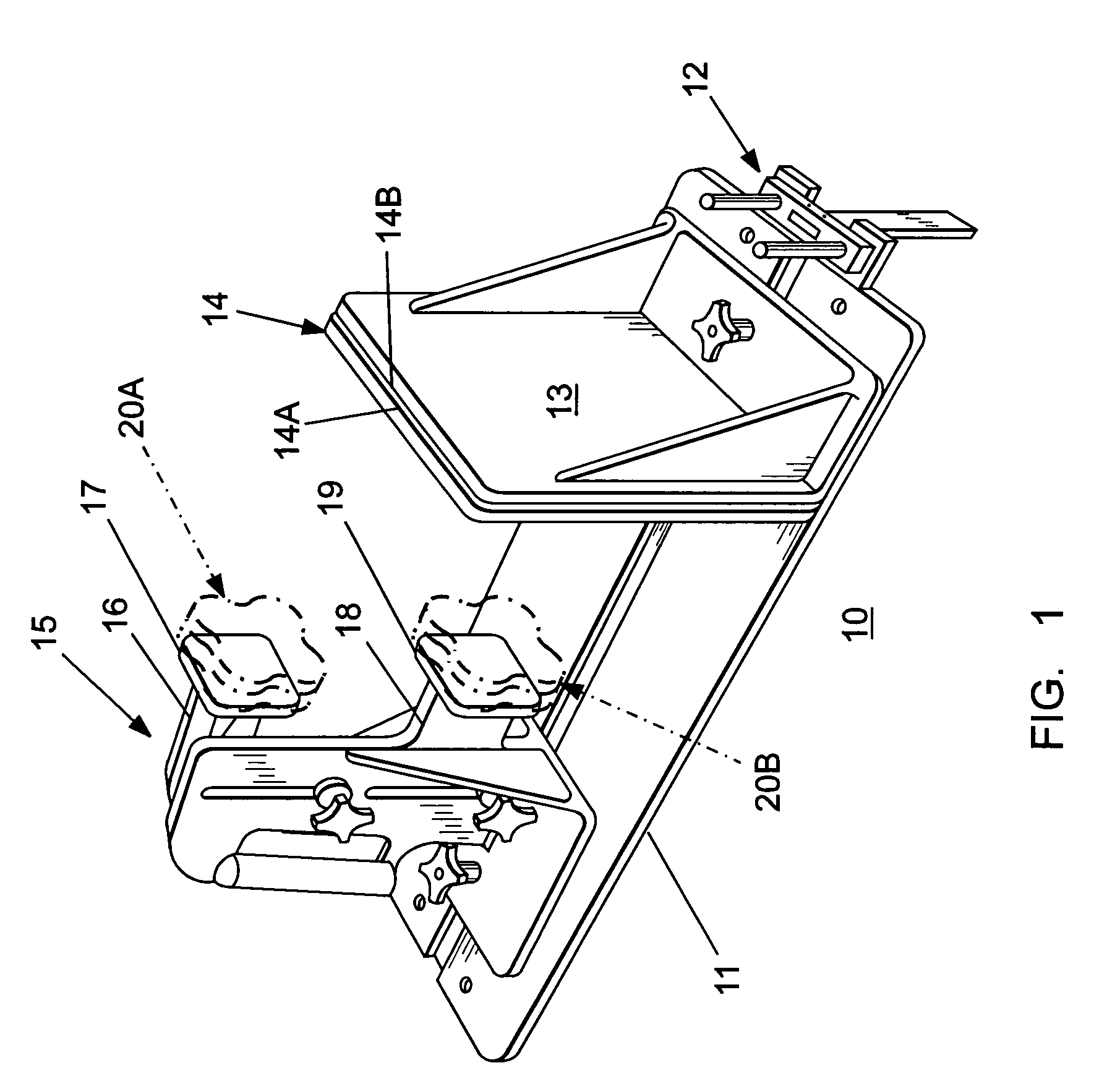
[0010]The surgical postioner device described within U.S. Pat. No. 6,820,621 is depicted at 10 in FIG. 1 in the form of a metal support plate 11 arranged for connection with a hospital bed support rail (not shown) via the side rail connector 12.

[0011]The patient rear support 13 is supported on the plate 11 and retains a rear pad 14 consisting of a first layer 14A of more porous polyurethane material than the second layer 14B for purposes which will be described below in greater detail.

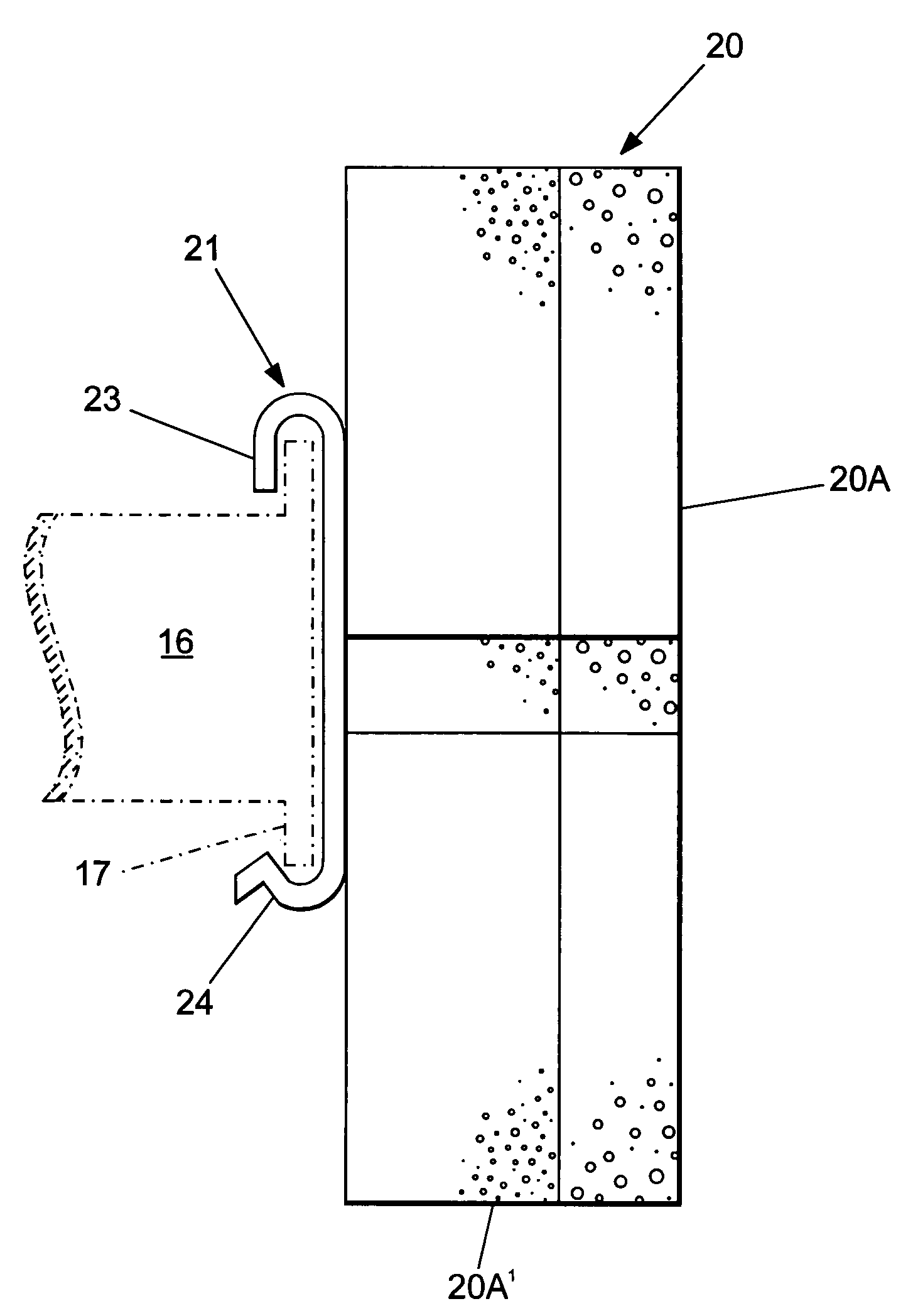
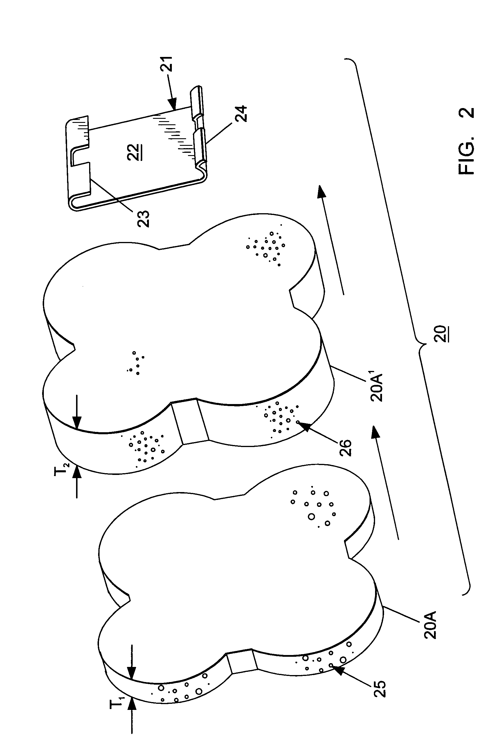
[0012]As described within aforementioned U.S. Pat. No. 6,820,621, a front support 15 is supported on the plate 11 and retains a top arm 16 terminating in a top support plate 17 and a bottom arm 18 terminating in a bottom support plate 19. The top and bottom dual compression pads, hereafter “pads”, 20A, 20B, shown in phantom are attached to the top and bottom plates 17, 19 in the manner to be described below.

[0013]The arrangement of the pads 20A and 20B relative to the connector clip or plate 21 is best...


PUM


Abstract

A dual compression foam pad arrangement for use with surgical postioner devices is formed from a single pair of cloverleaf-shaped foam pieces. The foam piece in contact with the patient is more porous than the foam piece in contact with the positioner support plate for greater patient comfort. A solid plastic connector clip connects the pad arrangement with the surgical postioner support in press-fit relation.

Description

BACKGROUND OF THE INVENTION[0001]Surgical postioner devices such as described within U.S. Pat. No. 6,820,621 entitled “Lateral Surgical Positioner Device” and U.S. Pat. No. 6,003,176 entitled “Universal Lateral Positioner” require foam pads arranged on the metal support plates that come in contact with the patient during hip surgery to prevent dermal abrasion.[0002]The foam pads usually consist of a plurality of pieces cemented together to form a square, round or rectangular structure defining a rectangular opening at one end to receive the metal support plate and a foam pad cemented to the opposite end for contact with the patient.[0003]Since the pads are held together by cement, the cement could possibly become pliable under heat and pressure causing replacement during the surgery process.[0004]Accordingly, one purpose of the invention is to disclose a method of providing a foam pad for use with hip procedure positioner devices, part of which is formed from a single pair of foam p...

Claims


Application Information

Patent Timeline
IPC IPC(8): A61G15/00
CPCA61G7/05A61G13/12A61G2200/322A61G13/123A61G2013/0081A61G13/1225A61G13/0081
Inventor BAILEY, JAMESWASLEY, ALANTAYLOR, MARTIN
Owner INNOVATIVE MEDICAL PRODS
Why Eureka
Try Eureka