
Removable wall-mounted back scrubber

a back scrubber and wall mount technology, applied in the field of back scrubbers, can solve the problems of not providing for a liquid soap dispenser attached to the back scrubber, prior art example is complicated to assemble and use, and limited use of hands and fingers, so as to achieve uniform adhesion effect during operation conditions

Inactive Publication Date: 2008-10-14
BORMISAEL
View PDF13 Cites 16 Cited by
  • Summary
  • Abstract
  • Description
  • Claims
  • Application Information

AI Technical Summary

Benefits of technology

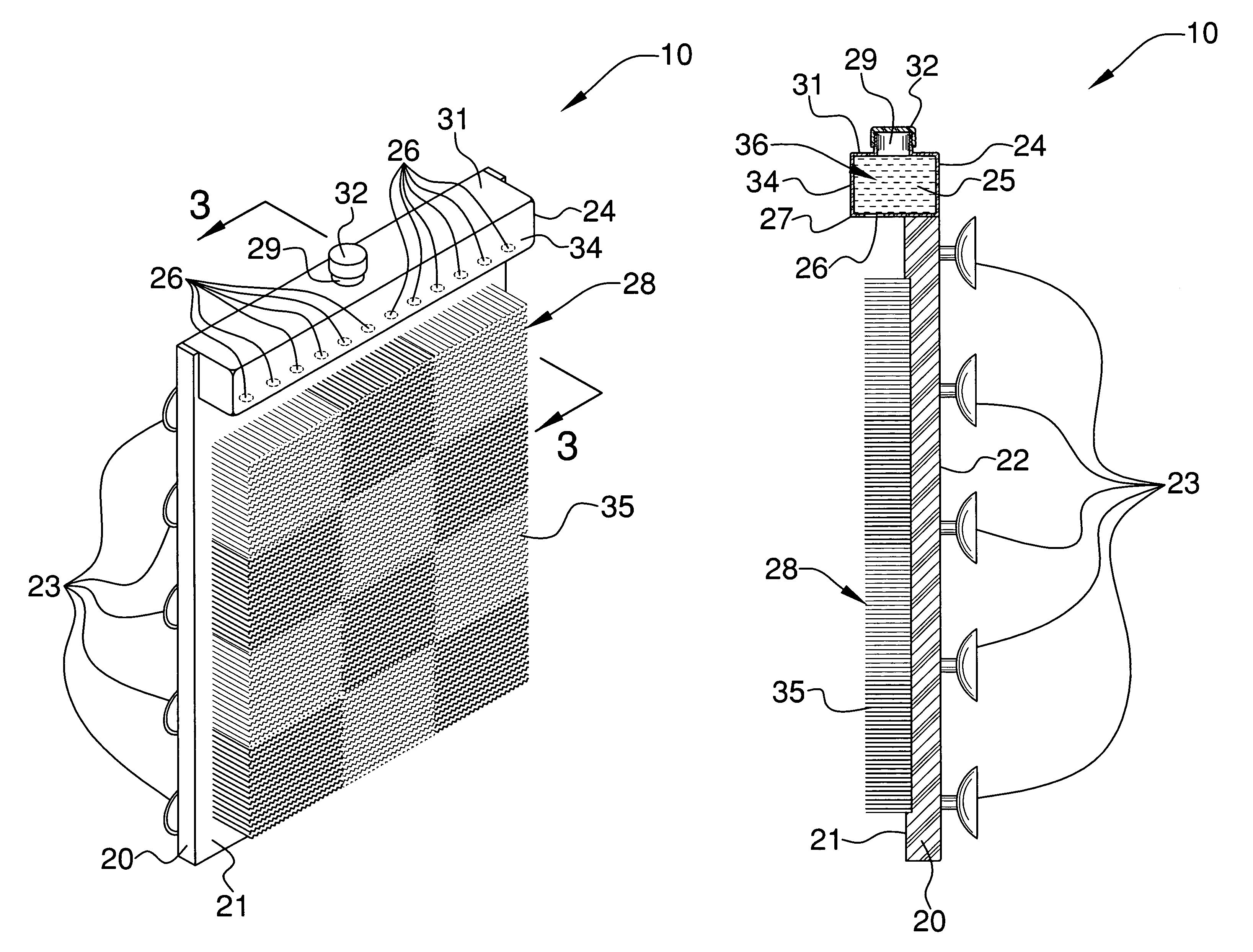
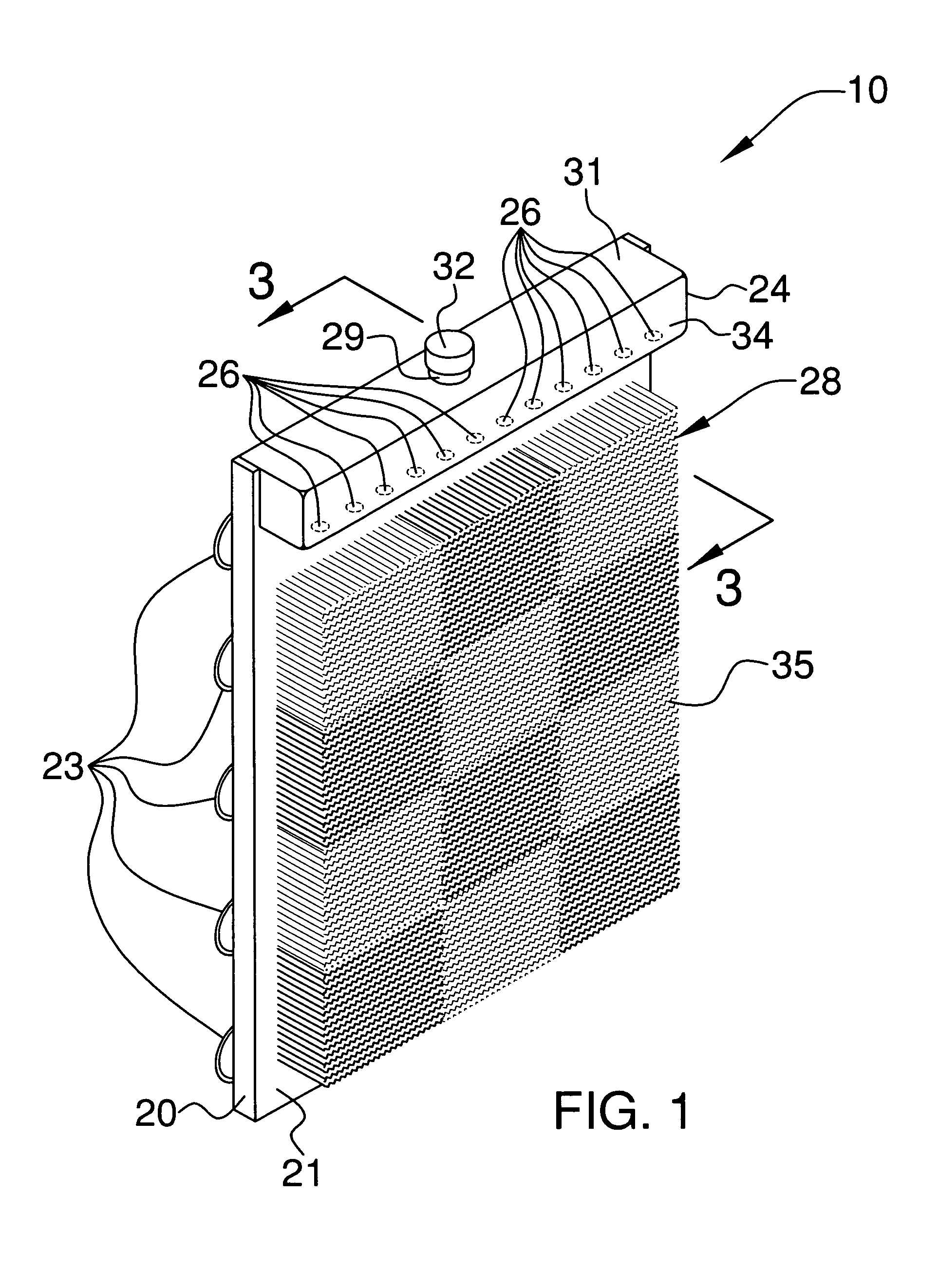
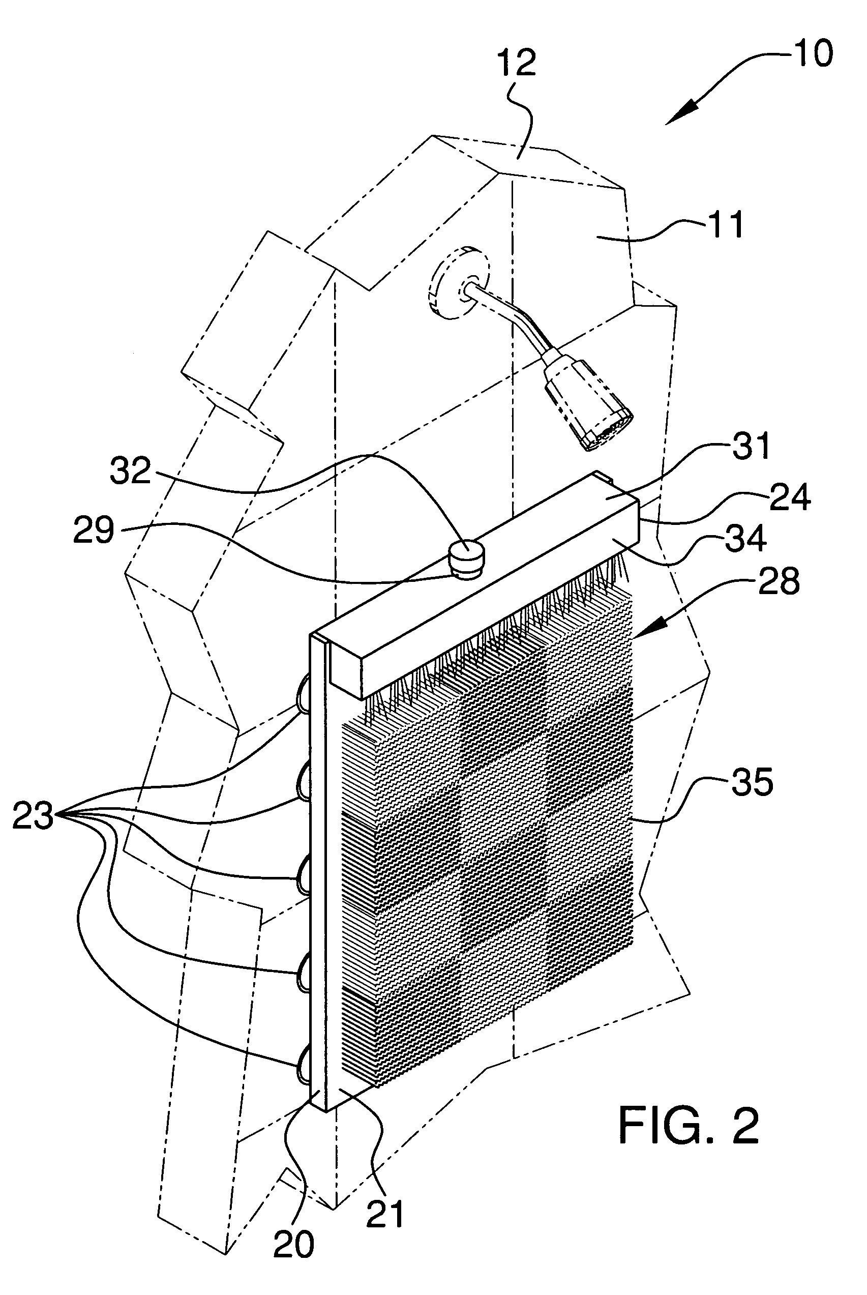
[0014]The back scrubber conveniently includes a reservoir detachably connected to an upper portion of the anchor plate. Such a reservoir includes a hollow chamber therein for effectively receiving and housing a predetermined quantity of a disinfecting agent. The reservoir further includes a plurality of equidistantly juxtaposed discharge outlets oriented along a bottom surface of the reservoir such that the disinfecting agent contained therein is advantageously discharged along a uniform vertical path traversing along an entire width of the cleaning surface. The reservoir is spaced from the suction cups and advantageously allows the user to slidably position the anchor plate along the vertical interior surface without prematurely agitating the disinfecting agent housed within the hollow chamber. The reservoir has a longitudinal length substantially equal to a latitudinal length of the cleaning surface.
[0016]The apparatus includes a plurality of suction cups that are directly connected to the rear surface of the anchor plate and extend rearwardly therefrom. Such a plurality of suction cups contacts the vertical interior surface of the shower stall. The suction cups are coextensively shaped for effectively providing uniform adhesion during operating conditions.
[0017]The apparatus includes a reservoir that includes a threaded inlet monolithically formed in a top surface of the reservoir and extending upwardly therefrom such that a quantity of disinfecting agent can be conveniently introduced into the hollow chamber therein. A threaded cap is removably mated to the inlet such that the disinfecting agent contained within the hollow chamber is effectively prevented from escaping the hollow chamber. Such a cap is centrally registered along a longitudinal length of the reservoir for equally discharging the disinfecting agent through an entire surface area of the hollow chamber.

Problems solved by technology

Unfortunately, this prior art example does not provide for a liquid soap dispenser attached to the back scrubber to facilitate ease of cleaning of the user's back.
Unfortunately, this prior art example is complicated to assemble and use.
Additionally, users with limited use of their hands and fingers may find it difficult to attach the necessary sponge or cloth for cleaning purposes.
This prior art example also does not provide for a liquid soap dispenser attached to the back scrubber to facilitate ease of cleaning of the user's back.

Method used


Image

  • Removable wall-mounted back scrubber
  • Removable wall-mounted back scrubber
  • Removable wall-mounted back scrubber

Examples


Embodiment Construction

[0027]The present invention will now be described more fully hereinafter with reference to the accompanying drawings, in which a preferred embodiment of the invention is shown. This invention may, however, be embodied in many different forms and should not be construed as limited to the embodiment set forth herein. Rather, this embodiment is provided so that this application will be thorough and complete, and will fully convey the true scope of the invention to those skilled in the art. Like numbers refer to like elements throughout the figures. Prime and double prime notations refer to alternate embodiments of like elements.

[0028]The apparatus of this invention is referred to generally in FIGS. 1-5 by the reference numerals 10, 10′ and 10″ and is intended to provide a removable wall-mounted back scrubber. It should be understood that the apparatus 10, 10′ and 10″ may be used to scrub many different types of body parts, and should not be limited in use to only scrubbing a user's bac...


PUM


Abstract

A removable wall-mounted back scrubber includes an anchor plate that has planar front and rear surfaces. The plate is vertically attached to a vertical interior surface of a shower stall. The plate has a plurality of equidistantly spaced suction cups coupled thereto. A reservoir is detachably connected to an upper portion of the plate and includes a hollow chamber therein. The reservoir has a longitudinal length substantially equal to a latitudinal length of the cleaning surface. A plurality of discharge outlets is oriented along a bottom surface of the reservoir. A cleaning surface is attached to the front surface of the plate and is juxtaposed orthogonally thereto. The cleaning surface extends orthogonally from the plate and terminates at a distance beyond the discharge outlets.

Description

CROSS REFERENCE TO RELATED APPLICATIONS[0001]Not Applicable.STATEMENT REGARDING FEDERALLY SPONSORED RESEARCH OR DEVELOPMENT[0002]Not Applicable.REFERENCE TO A MICROFICHE APPENDIX[0003]Not Applicable.BACKGROUND OF THE INVENTION[0004]1. Technical Field[0005]This invention relates to back scrubbers and, more particularly, to a removable wall-mounted back scrubber for cleansing a user's back while showering.[0006]2. Prior Art[0007]Various devices for attachment to a bathroom shower or tub wall presently exist for the purpose of cleaning or massaging inaccessible areas of a person's body, particularly the back. Such devices assist the elderly, persons with arthritis and others with impaired mobility. Otherwise unimpaired persons also benefit from the presently known devices which make hard-to-reach areas of a person accessible to cleaning or massaging.[0008]One prior art example shows a wall-mountable back scrubber comprising a rectangular base unit with adapter mounts and suction cups a...

Claims


Application Information

Patent Timeline
IPC IPC(8): A47K7/03
CPCA47K7/024
Inventor BORGES, MISAEL
Owner BORMISAEL
Learn More