Fluid property sensors

a technology of fluid property and sensors, which is applied in the direction of instruments, surveyors, borehole/well accessories, etc., can solve the problems of high cost of retrieving downhole samples, high difficulty in handling samples at the surface under downhole pressure and temperature conditions, and the chemical composition of downhole fluids that closely resemble downhole fluids

Inactive Publication Date: 2008-10-14
SCHLUMBERGER TECH CORP
View PDF16 Cites 53 Cited by
  • Summary
  • Abstract
  • Description
  • Claims
  • Application Information

AI Technical Summary

Benefits of technology

The invention is a MEMS based fluid sensor that has a planar member made from a substrate material. It also has an electrical conductor and a gauge on the planar member. The gauge is designed to measure a physical effect on the planar member that is caused by the fluid in contact with it. This allows for the detection and measurement of properties of the fluid.

Problems solved by technology

The patent text discusses the importance of understanding the density, viscosity, and chemical composition of reservoir fluids in the oil exploration and production industries. However, it is difficult to obtain a sample that closely resembles the downhole fluid chemical composition due to the volatility of lighter hydrocarbons, solids deposition, and drilling fluid contamination. The cost of retrieving a downhole sample and the difficulty of handling samples at the surface under downhole pressure and temperature conditions are both very high. Making measurements downhole will accelerate the evaluation process and reduce total costs. The technical problem is to develop a fluid sensor that can operate accurately in this complicated and harsh environment.

Method used


Image

  • Fluid property sensors
  • Fluid property sensors
  • Fluid property sensors

Examples


Embodiment Construction

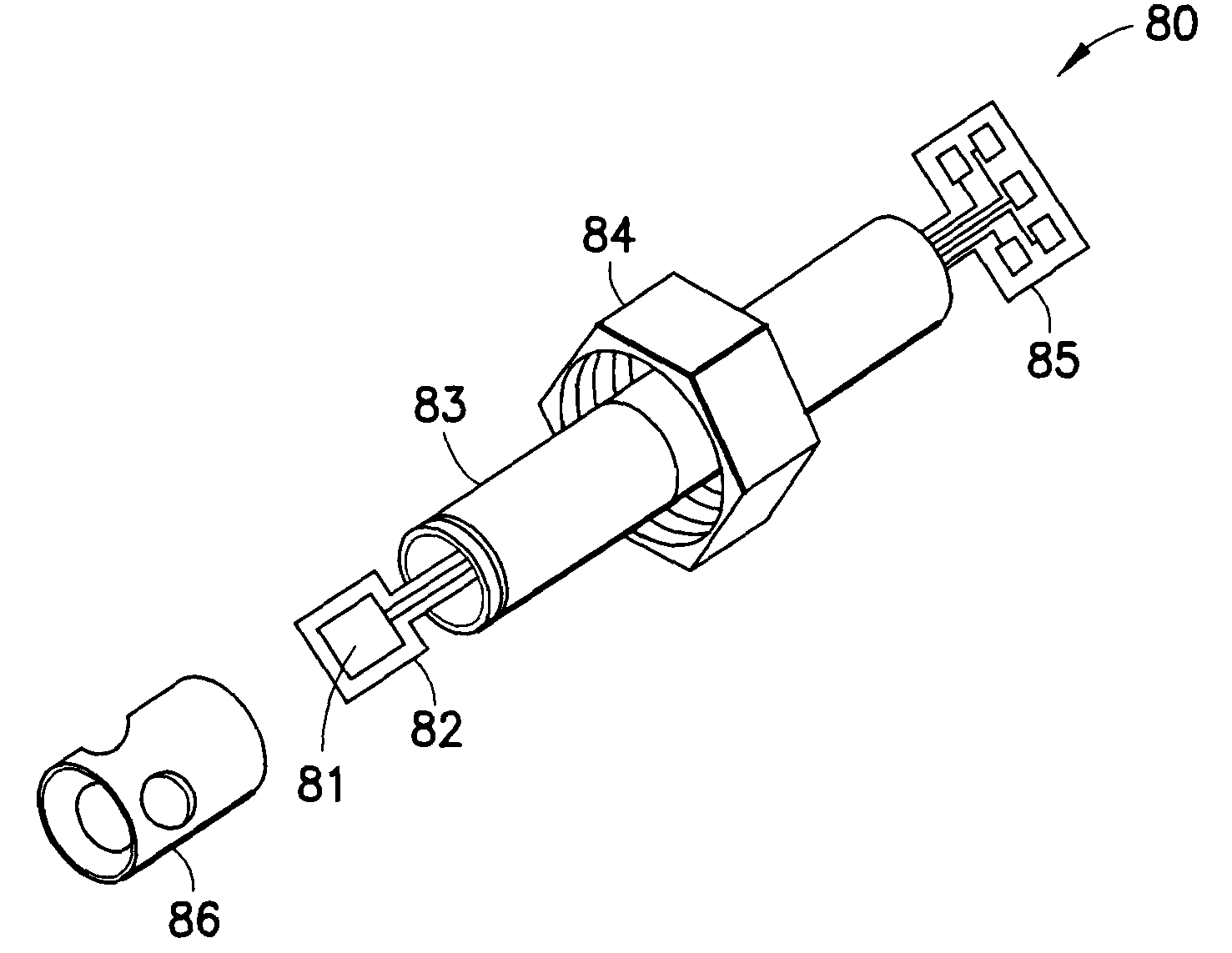
[0024]The present invention describes a range of electromechanical sensors that have been adapted for analyzing and measuring thermo-physical properties of oilfield fluids under downhole conditions. The electromechanical sensors of this invention are micro-machined out of a substrate material and are fabricated using technologies that have been developed to produce electronic integrated circuit (IC) devices at low cost and in large quantities (batch fabrication). Devices of this type are typically referred to as Micro-Electro-Mechanical Systems (MEMS) devices, and the inventors believe the present invention describes the first application of MEMS technology to downhole oilfield fluid property sensing.

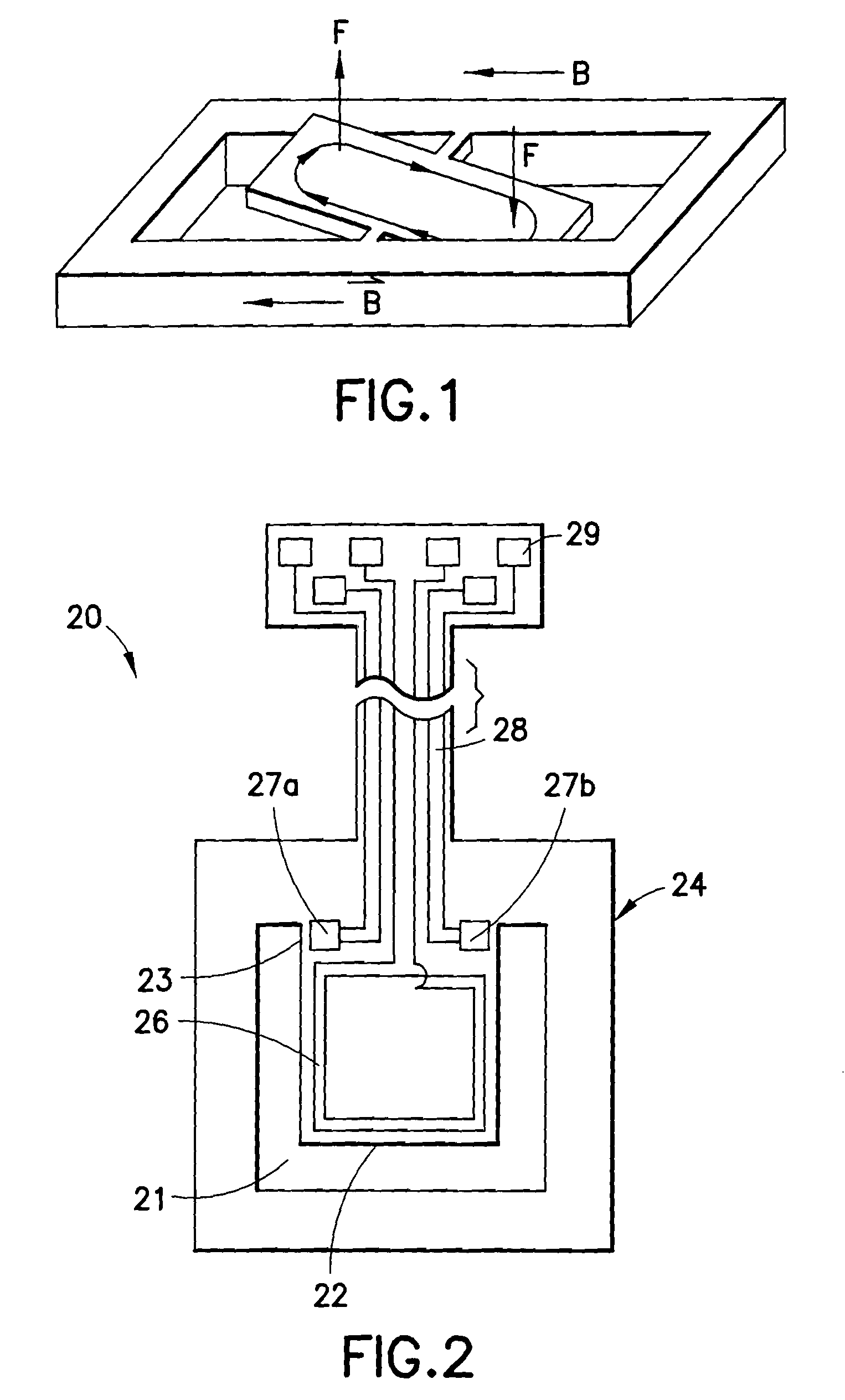
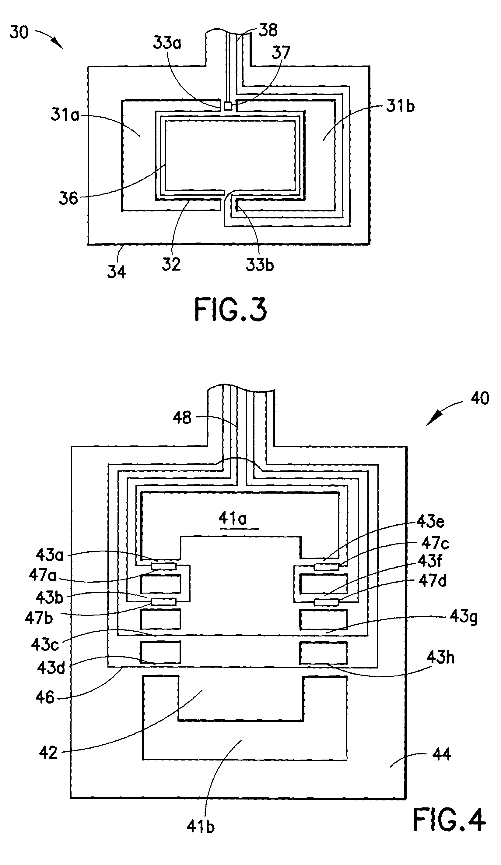
[0025]The MEMS based sensors of the present invention include a planar member machined from a substrate material, an electrical conductor formed at least partly on the planar member, and some sort of gauge formed on the planar member. When the planar member is put into contact with a fl...


PUM


Abstract

Micro-Electro Mechanical Systems (MEMS) based fluid sensors adapted to measure physical properties of oilfield reservoir fluids under downhole conditions. Certain embodiments of the invention may be characterized as a MEMS based reservoir fluid sensor adapted for downhole conditions having a planar member machined from a substrate material, an electrical conductor formed at least partly on the planar member; and a gauge formed on the planar member and adapted to measure a physical effect on the planar member, the physical effect being indicative of a property of a fluid in contact with the planar member.

Description


Claims


Application Information

Patent Timeline
Owner SCHLUMBERGER TECH CORP
Why Eureka
Try Eureka