Illumination device

a technology of a screw and a screw body, which is applied in the direction of instruments, transportation and packaging, display means, etc., can solve the problems of troublesome application of adhesive, affecting the appearance of the instrument, so as to achieve convenient mounting, easy mounting, and easy molded

Active Publication Date: 2008-10-14
ALPS ALPINE CO LTD
View PDF5 Cites 4 Cited by
  • Summary
  • Abstract
  • Description
  • Claims
  • Application Information

AI Technical Summary

Benefits of technology

[0009]The present invention has been made in view of these circumstances of the related art. An object of the invention is to provide an illumination device in which a light guide plate can be easily and reliably held in a tubular case.
[0011]In the illumination device having the above-described configuration, the flat light guide plate is convexly bent by being retained by the retaining projections and the push-up projections provided on the inner surface of the tubular case. The light guide plate is held while being elastically urged against the retaining projections and the push-up projections by a bending force. Therefore, the light guide plate can be easily mounted in the tubular case without using an adhesive. Moreover, rattling of the light guide plate is prevented, and a reliable holding structure can be achieved.
[0014]Preferably, upper surfaces of the retaining projections are tapered and inclined downwardly. In this case, the outer edge of the light guide plate can be easily put below the retaining projections along the tapered upper surfaces.
[0015]Preferably, a stepped portion continuously extends along an inner surface of the tubular case along an inner periphery of the tubular case, and the push-up projections are provided on the stepped portion. In this case, when the light guide plate is put in the tubular case from the upper opening, the outer edge of the light guide plate comes into contact with an upper surface of the stepped portion, and the light guide plate is prevented from being inserted further. Therefore, the light guide plate can be easily mounted between the retaining projections and the push-up projections of the tubular case.
[0016]Preferably, a plurality of punched holes are provided in the tubular case, which extend from an outer surface of the tubular case to lower surfaces of the retaining projections. Outer open ends of the punched holes are covered with the control knob when the control knob is snap-fitted on the tubular case. In this case, a tubular case having an undercut shape can be easily molded by using the punched holes. Moreover, since the punched holes provided in the outer surfaces of the tubular case are closed or sealed by the control knob, dust, moisture, and the like are prevented from entering the tubular case through the punched holes.
[0017]In the illumination device according to the aspect of the present invention, the light guide plate interposed between the light source and the display portion is convexly bent by being retained by the retaining projections and the push-up projections provided on the inner surface of the tubular case, and the light guide plate is held while being elastically urged against the retaining projections and the push-up projections by a bending force. Therefore, the light guide plate can be easily mounted in the tubular case without using an adhesive. Moreover, rattling of the light guide plate is prevented, and a reliable holding structure can be achieved.

Problems solved by technology

For example, when an adhesive, which is known as a general fixing means, is used, a step of applying the adhesive is troublesome, and the adhesive strength declines with time.
However, since the control knob having the projections is combined with the tubular case having the stepped portion by snap fitting, if the distance between the stepped portion and the projections is smaller than the thickness of the light guide plate within the dimensional tolerance, it is quite difficult to snap-fit the control knob and the tubular case.
As a result, the light guide plate rattles between the stepped portion and the projections, thus causing an abnormal noise during driving.

Method used


Image

  • Illumination device
  • Illumination device
  • Illumination device

Examples


Embodiment Construction

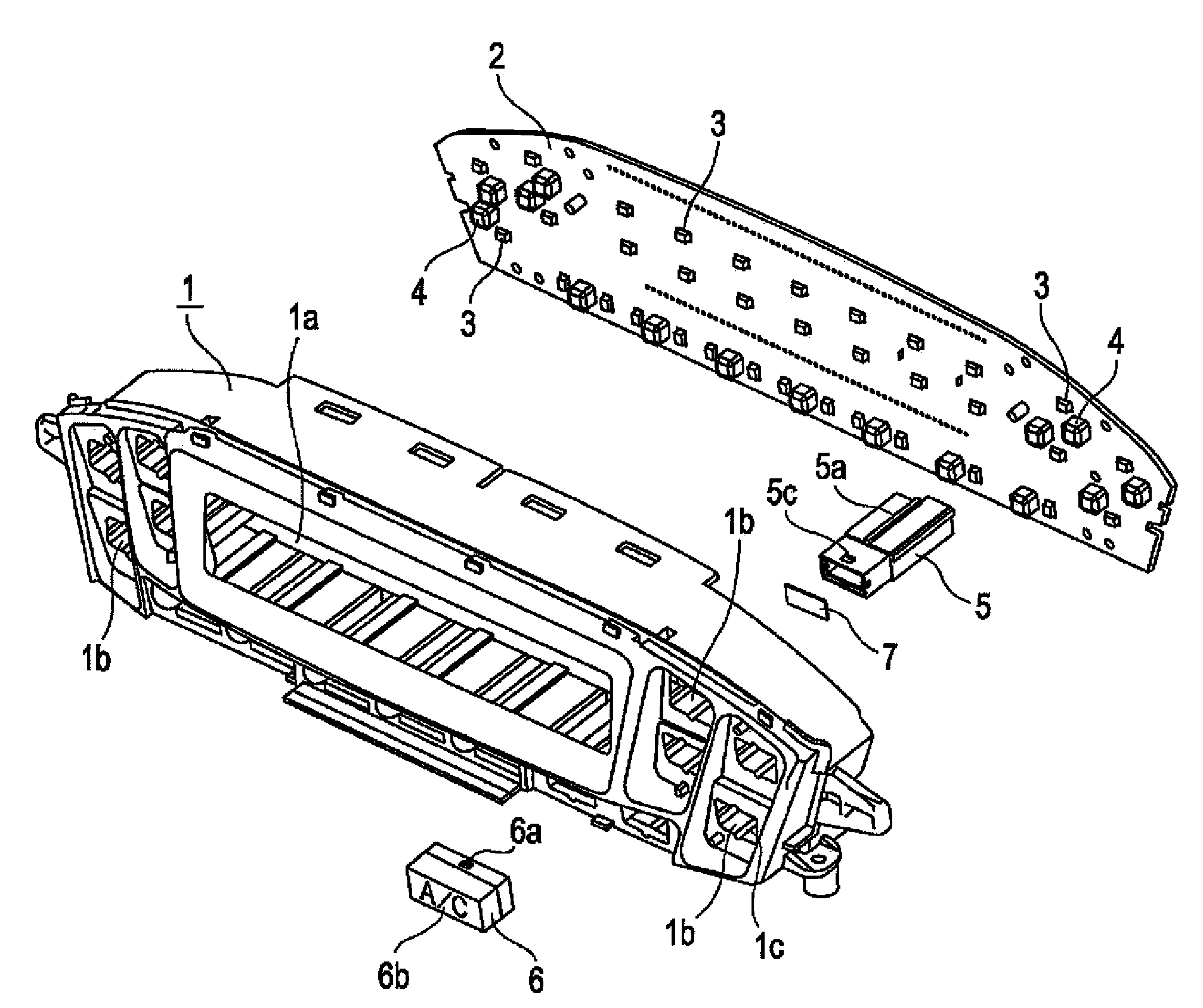
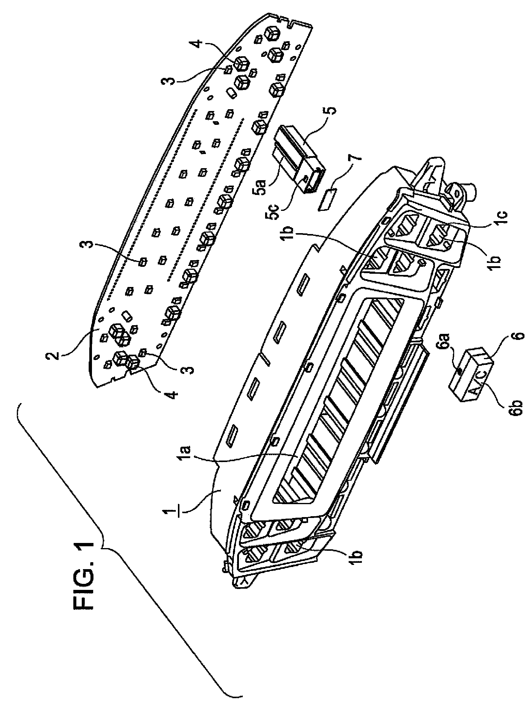
[0023]An illumination device according to an embodiment of the present invention will be described below with reference to FIGS. 1 to 5. In these figures, the illumination device is applied to a control panel.

[0024]Referring to these figures, a housing 1 serving as an outer shell of the control panel is provided in, for example, an instrument panel or a central console box of a vehicle. The housing 1 includes a relatively large opening 1a, and a plurality of through holes 1b provided around the opening 1a. A printed circuit board 2 is attached to a rear end of the housing 1. Multiple LEDs 3 and push switches 4 are mounted on the printed circuit board 2 such that the LEDs 3 oppose the opening 1a and the through holes 1b, and the push switches 4 oppose the through holes 1b. The LEDs 3 opposing the opening 1a function as light sources for backlighting an LCD that is provided in the opening 1a.

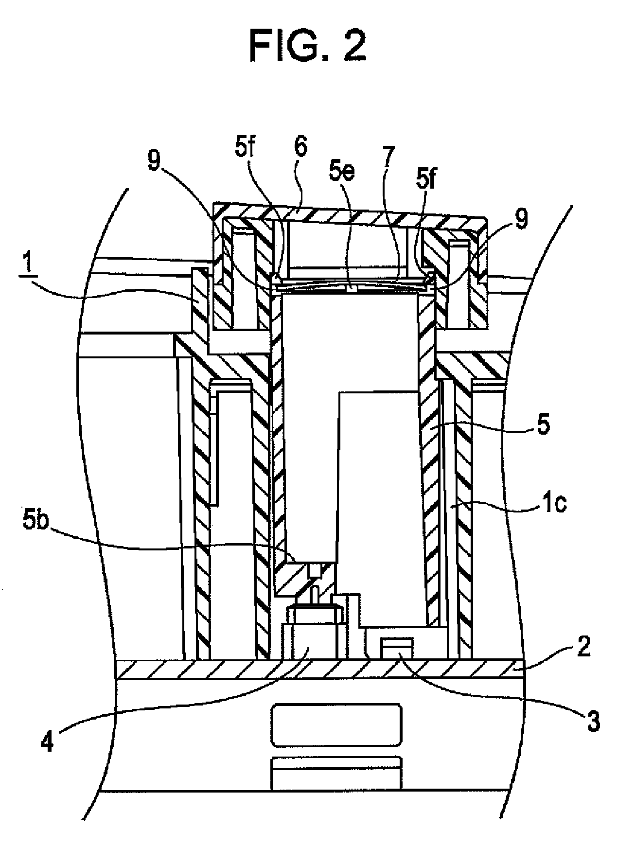
[0025]A tubular case 5 made of synthetic resin is provided in each of the through holes 1b of...


PUM


Abstract

An illumination device includes a control knob having a display portion, a tubular case combined with a back side of the control knob, a light guide plate attached to seal an upper opening of the tubular case, and LEDs disposed at a lower opening of the tubular case. Light emitted from the LEDs is applied to the display portion through the light guide plate. A plurality of retaining projections and a plurality of push-up projections are provided on an inner surface of the tubular case adjacent to the upper opening. An upper surface of an outer edge of the light guide plate is retained by lower ends of the retaining projections, and a lower surface of the outer edge is pushed up by upper ends of the push-up projections so that the light guide plate is held inside the tubular case while being bent upwardly.

Description

[0001]This application claims the benefit of priority under 35 U.S.C. § 119 to Japanese Patent Application No. 2006-052770, filed Feb. 28, 2006, which is hereby incorporated by reference in its entirety.BACKGROUND OF THE INVENTION[0002]1. Field of the Invention[0003]The present invention relates to an illumination device that illuminates a display portion of a control knob provided in, for example, an on-vehicle control panel.[0004]2. Description of the Related Art[0005]In control panels used in on-vehicle air conditioning systems and audio systems, an operator (occupant) selectively presses or rotates a plurality of control knobs, and an inherent function assigned to the control knob is thereby performed. Normally, the control knobs have display portions corresponding to their respective assigned functions. An illumination device is mounted so as to allow the display portions to be viewed even in an unlit environment.[0006]Japanese Unexamined Patent Application Publication No. 2004...

Claims


Application Information

Patent Timeline
Patent Type & Authority Patents(United States)
IPC IPC(8): G01D11/28
CPCH01H13/023Y10S362/80
Inventor IMAI, TOSHIO
Owner ALPS ALPINE CO LTD
Why Eureka
Try Eureka