System for securing a suture

a technology for securing systems and sutures, applied in wound clamps, medical science, surgery, etc., can solve the problems of difficult formation of small body cavities, time-consuming tying of knots, and relatively unreliable means of securely maintaining sutures in tissu

Inactive Publication Date: 2008-10-14
GREEN DAVID T
View PDF20 Cites 57 Cited by
  • Summary
  • Abstract
  • Description
  • Claims
  • Application Information

AI Technical Summary

Benefits of technology

[0010]Preferably, the clip applicator further includes means for severing or cutting the suture at a location proximal to the suture clip. The severing means is positioned and preferably operates to cut the suture after the suture clip is dislodged from the mounting fixture. The mounting fixture is oriented at an angle with respect to the longitudinal axis of the elongated body of the clip applicator. The helps to properly align and position the clip at the incision site, so that it is flush against the vessel wall or body tissue that has been sutured.
[0012]The subject invention is also directed to a new and useful deformable suture clip. The suture clip includes a proximal body portion having a pair of abutting surfaces configured for movement between an open position and a normally closed position. In the open position, a suture can pass between the abutting surfaces. In the normally closed position, the suture can be securely clamped between the pair of abutting surfaces. The suture clip further includes a distal body portion defining, at least in part, deformable means for facilitating the movement of the pair of abutting surfaces between the open and closed positions.

Problems solved by technology

Knots are time consuming to tie, difficult to form in small body cavities and are a relatively unreliable means of securely maintaining a suture in tissue.
This technique is time consuming, uncomfortable and can cause thrombosis, thereby presenting a danger to the patient.
However, because the procedure is performed percutaneously through a small entrance wound in the patient's leg, properly tying a knot to securely fasten the suture and close the incision is a difficult task.
For that matter, placing a clip on the suture at the site of the incision in the blood vessel wall is even more difficult, because there is no direct line of sight to ensure the proper placement of the clip.

Method used


Image

  • System for securing a suture
  • System for securing a suture
  • System for securing a suture

Examples


Embodiment Construction

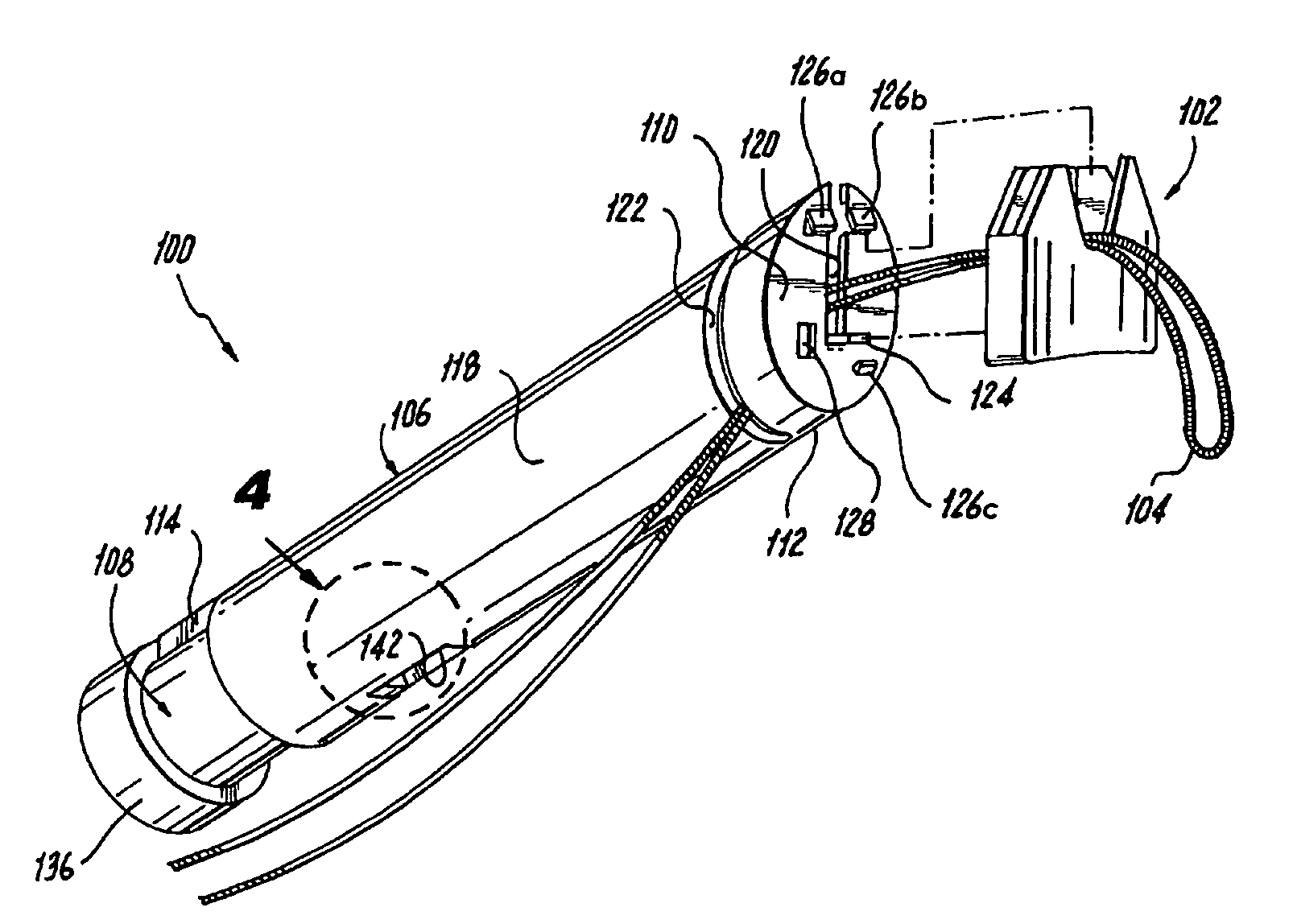
[0035]Referring now to the drawings wherein like reference numerals identify similar structural elements of the apparatus disclosed herein, there is illustrated in FIG. 1 a suture clip applicator constructed in accordance with a preferred embodiment of the subject invention and designated generally by reference numeral 100. In the specification that follows the term “distal” shall refer to the end of the applicator that is nearest to the surgical site, while the term “proximal” shall refer to the end of the applicator that is farthest from the surgical site.

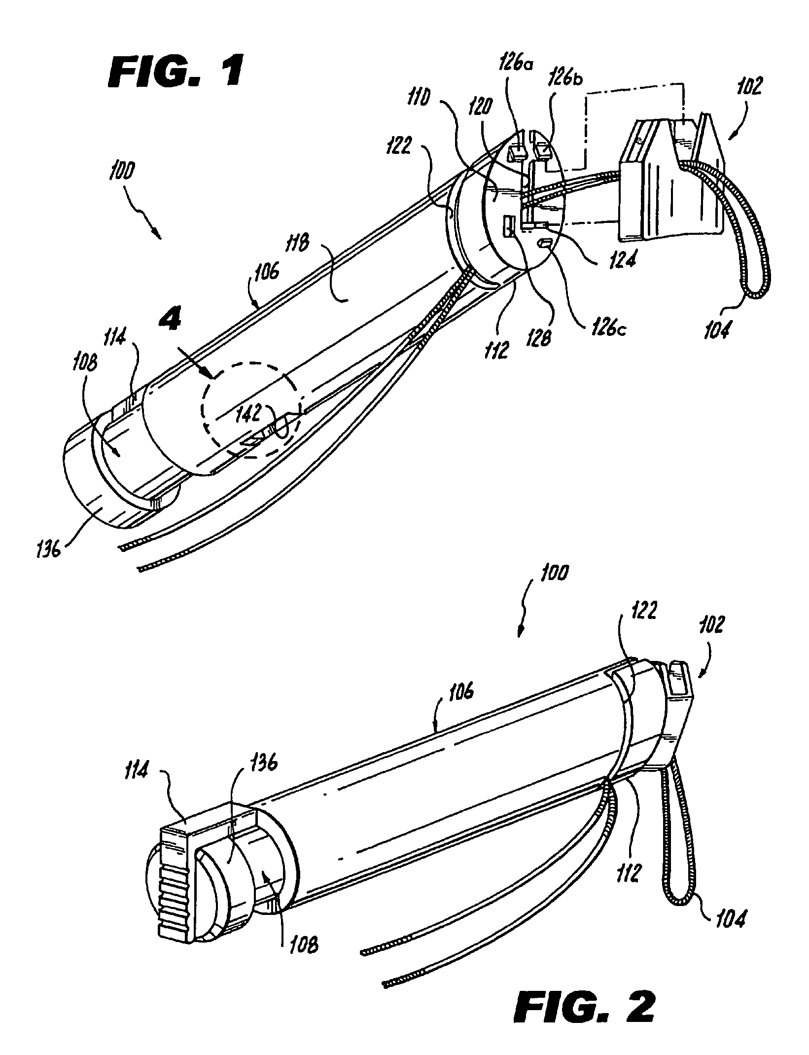
[0036]Referring to FIGS. 1 and 2, clip applicator 100 is adapted and configured to apply or otherwise secure a deformable suture clip 102 to a suture at a desired location, to secure the suture in place and ensure effective wound closure. It is envisioned that the clip applicator 100 of the subject invention may be employed in conjunction with a percutaneous procedure, for example, to secure a suture used to close an opening in a...


PUM


Abstract

A system is disclosed for securing a suture. The system includes a deformable suture clip having a pair of closely spaced panels configured for movement between an open position wherein a suture can pass between the two panels and a closed position wherein the suture can be securely clamped between the two panels. The system further includes a clip applicator having an elongated body defining opposed proximal and distal end portions. The distal end portion of the body includes a mounting fixture having structure for supporting the suture clip in an open position. The clip applicator further includes a mechanism for dislodging the suture clip from the mounting fixture, such that the panels of the clip move to the closed position to securely clamp the suture therebetween.

Description

BACKGROUND OF THE INVENTION[0001]1. Field of the Invention[0002]The subject disclosure relates to a system for securing a suture, and more particularly, to a surgical apparatus for applying a deformable suture clip to a suture used to close a surgical incision or wound formed in a blood vessel or body tissue.[0003]2. Background of the Related Art[0004]Sutures have long been used to close wounds and surgical incisions in body tissue. It is common practice to secure a suture in body tissue by tying one or more knots therein. Knots are time consuming to tie, difficult to form in small body cavities and are a relatively unreliable means of securely maintaining a suture in tissue. In view of these shortcomings, various devices and fasteners have been developed to positively secure a suture in place following a surgical procedure.[0005]For example, U.S. Pat. No. 6,077,277 to Mollenauer et al. discloses a device for joining suture segments together. The device has a pair of grasping jaws w...

Claims


Application Information

Patent Timeline
Patent Type & Authority Patents(United States)
IPC IPC(8): A61B17/04
CPCA61B17/0487A61B17/0467A61B2017/0454A61B2017/0488
Inventor GREEN, DAVID T.
Owner GREEN DAVID T
Why Eureka
Try Eureka