Scanning examination apparatus, lens unit, and objective-lens adaptor

a scanning examination and lens unit technology, applied in the field of scanning examination apparatus, can solve the problems of difficult to determine the optical axis position of the objective lens from the light spot, difficult to align the position of the optical axis of the objective lens and the site to be examined on the specimen, and difficult to determine the optical axis position of the objective lens. the effect of quick and easy confirmation of the optical axis position, quick and easy positioning of the objective lens

Inactive Publication Date: 2008-10-14
OLYMPUS CORP
View PDF16 Cites 18 Cited by
  • Summary
  • Abstract
  • Description
  • Claims
  • Application Information

AI Technical Summary

Benefits of technology

[0012]The present invention has been conceived in light of the circumstances described above, and an object thereof if to provide a scanning examination apparatus that is capable of quickly and easily confirming the optical axis position of an objective lens with respect to a site to be examined on a specimen, and that can rapidly perform positioning of the objective lens with respect to the specimen during a preparation stage and can quickly obtain a desired image during an observation stage.
[0013]Furthermore, it is another object of the present invention to provide a lens unit and an objective-lens adaptor that enable simple and comparatively long-term in-vivo examination of biological tissue, such as cells and muscle tissue, or the conditions below the surface of various internal organs, such as the heart, liver, or brain, of mammals such as small laboratory animals and the like.

Problems solved by technology

Therefore, in such a scanning examination apparatus, there is a problem in that it is difficult to align the position of the optical axis of the objective lens and the site to be examined on the specimen.
Furthermore, because the light radiated from the light source is two-dimensionally scanned on the specimen by the proximity galvanometer mirrors, even though light is emitted in the preparation stage, it is difficult to determine the optical axis position of the objective lens from the light spot, which is continually moving.
It is particularly difficult to determine the position of the optical axis of the objective lens when the light from the light source is laser light.
For example, when the wavelength of the laser light is not in the visible region, it is not possible to confirm the radiated region, similar to the above.
Moreover, even if the wavelength of the laser light is in the visible region, it is difficult to perform alignment due to the dazzle effect peculiar to laser light.
However, in a standard microscope objective lens unit, the outer diameter of the lens barrel containing the lenses is large and is therefore not suitable for in-vivo examination of the conditions below the surface of a biological specimen, such as inside a laboratory animal or the like.
In such a case, since the region to be examined is directly behind the incision or hole in the surface of the specimen, the specimen may be significantly damaged by forming such an incision or hole, and therefore it is difficult to perform time-lapse observation over a long period of time.
Since this method involves sewing up the region where the incision or hole is formed after examination and making another incision the next time examination is carried out, the biological specimen is inevitably damaged.
Therefore, this method suffers from the disadvantage that it is difficult to examine the specimen under normal conditions over an extended period of time.

Method used


Image

  • Scanning examination apparatus, lens unit, and objective-lens adaptor
  • Scanning examination apparatus, lens unit, and objective-lens adaptor
  • Scanning examination apparatus, lens unit, and objective-lens adaptor

Examples


first embodiment

[0063]A scanning examination apparatus 1 according to the present invention will be described below with reference to FIGS. 1 to 3.

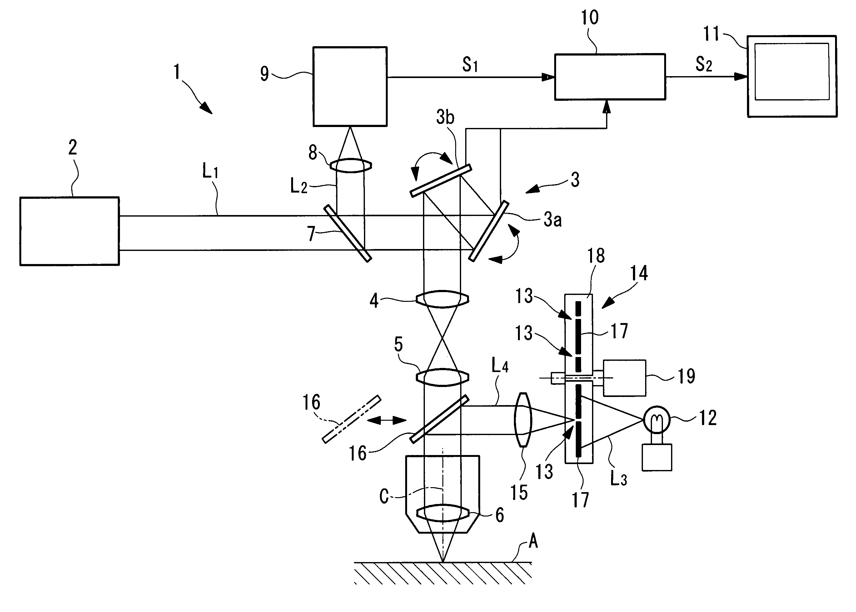
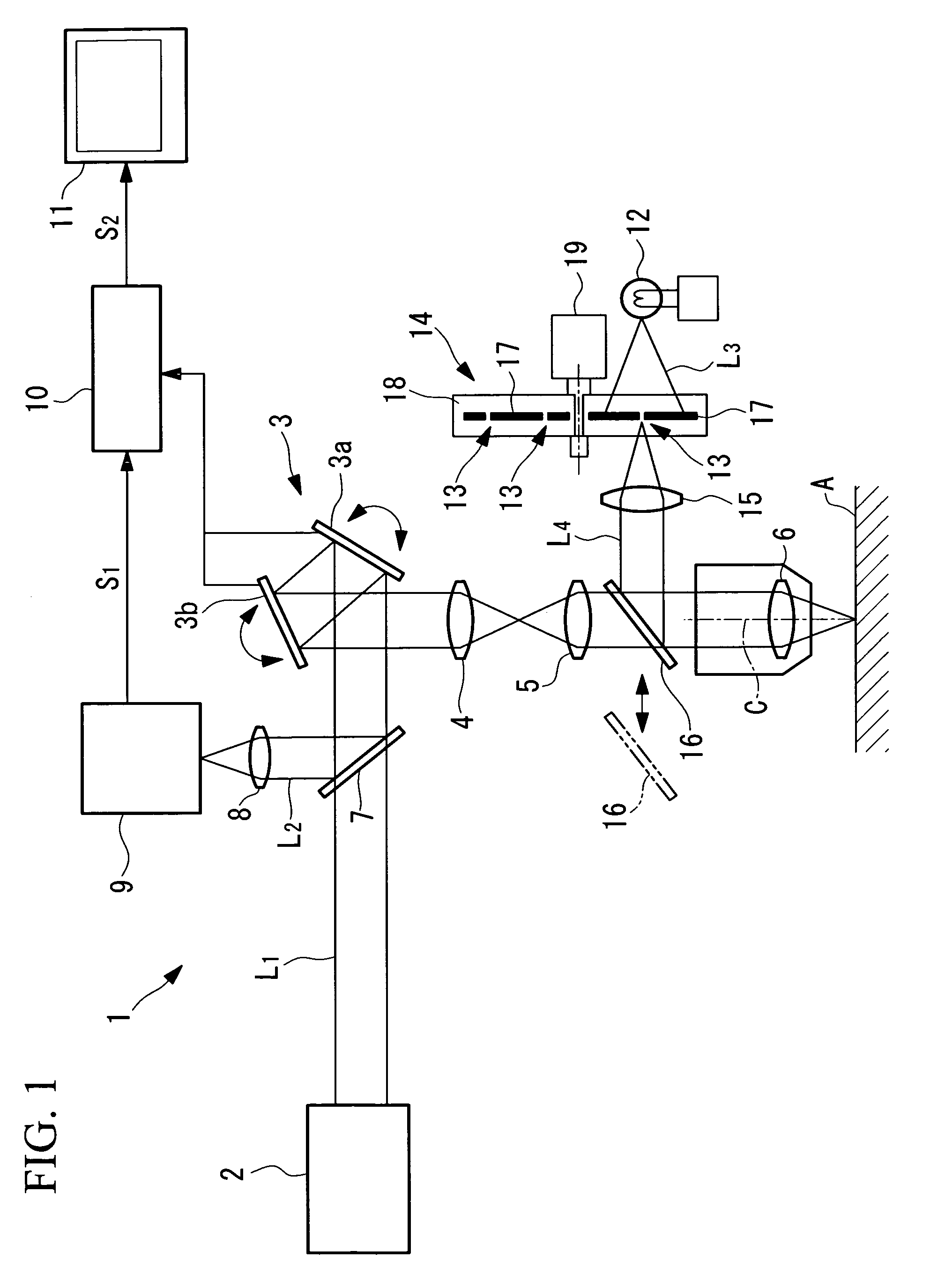
[0064]As shown in FIG. 1, the scanning examination apparatus 1 according to this embodiment, which is a laser-scanning fluorescence microscope apparatus, includes a laser light source (first light source) 2 for emitting laser light L1; a scanner (light scanning unit) 3 for two-dimensionally scanning the laser light L1 emitted from the laser light source 2; a pupil-projection lens 4 for focusing the laser light L1 scanned by the scanner 3 to form an intermediate image; an image-forming lens 5 for collecting the laser light L1 forming the intermediate image and converting it to a substantially collimated beam; and an objective lens 6 for re-imaging the laser light L1 collected by the image-forming lens 5 at a specimen A.

[0065]The scanner 3 is formed of so-called proximity galvanometer mirrors in which galvanometer mirrors 3a and 3b, which are provided so a...

second embodiment

[0088]Next, a scanning examination apparatus 20 according to the present invention will be described below with reference to FIGS. 4 and 5.

[0089]In the description of this embodiment, parts having the same configuration as those in the scanning examination apparatus 1 according to the first embodiment described above are assigned the same reference numerals, and a description thereof shall be omitted.

[0090]The scanning examination apparatus 20 according to this embodiment differs from the first embodiment in that, instead of the mirror 16 in the scanning examination apparatus 1 according to the first embodiment, a half-mirror 21 is permanently disposed between the image-forming lens 5 and the objective lens 6, as shown in FIG. 4.

[0091]The operation of the scanning examination apparatus 20 according to this embodiment, having such a configuration, will be described below.

[0092]With the scanning examination apparatus 20 according to this embodiment, during a preparation stage, when th...

third embodiment

[0100]Next, a scanning examination apparatus according to the present invention will be described below with reference to FIGS. 6 and 7.

[0101]The scanning examination apparatus according to this embodiment is a microscope apparatus including the structure of the scanning examination apparatus 1 described in the first embodiment.

[0102]More specifically, the scanning examination apparatus of this embodiment includes an examination apparatus main body (not shown in the drawings) and a microscope objective lens unit 101 (see FIG. 6) that is removably attached to the examination apparatus main body.

[0103]As shown in FIG. 6, the microscope objective lens unit 101 includes an infinity optical lens group 102 (objective lens 6) formed of a plurality of lenses, a lens barrel 103 for accommodating the infinity optical lens group 102, and a pointed insertion member 104 disposed at the end of the lens barrel 103. The lens barrel 103 is provided with a threaded mount 105 for removably attaching t...


PUM


Abstract

It is possible to easily and accurately confirm the position of an optical axis of an objective lens relative to an examination site on a specimen, and positioning of the objective relative to the specimen can be carried out rapidly in a preparation stage. The invention provides scanning examination apparatus comprising a first light source; a light scanning unit configured to scan light from the first light source on a specimen; an objective lens configured to form an image of the light scanned in the light scanning unit at the specimen; a light-detecting unit configured to detect return light emitted from the specimen; a second light source configured to emit visible light; a deflecting optical element, disposed between the light scanning unit and the objective lens, for making visible light emitted from the second light source enter the objective lens along an optical axis of the objective lens; and a beam-shaping unit configured to form the visible light from the second light source, which is irradiated onto a surface of the specimen via the objective lens using the deflecting optical element, into a pattern that enables the optical axis of the objective lens to be indicated.

Description

BACKGROUND OF THE INVENTION[0001]1. Field of the Invention[0002]The present invention relates to a scanning examination apparatus, lens unit, and objective-lens adaptor. This application is based on Japanese Patent Applications Nos. 2005-084262 and 2005-084263, the contents of which are incorporated herein by reference.[0003]2. Description of Related Art[0004]Known scanning examination apparatuses in the related art include, for example, scanning laser microscopes (for example, see Japanese Unexamined Patent Application Publication No. 2000-275529).[0005]A scanning laser microscope two-dimensionally scans a specimen by imaging laser light emitted from a laser light source onto the specimen using an objective lens, via proximity galvanometer mirrors. By scanning the specimen with laser light in this way, the scanning laser microscope splits off fluorescence generated in the specimen and returning via the objective lens and the proximity galvanometer mirrors from the incident laser li...

Claims


Application Information

Patent Timeline
Patent Type & Authority Patents(United States)
IPC IPC(8): G02B26/08G02B21/06
CPCA61B5/0059G02B21/0012G02B21/0028G02B21/006G02B26/0816A61B5/0068
Inventor NAGASAWA, NOBUYUKITANIKAWA, YOSHIHISAOSA, KAZUHIKOSAITO, YOSHIHARU
Owner OLYMPUS CORP
Why Eureka
Try Eureka