Wind vane device

a wind vane and wind technology, applied in the direction of instruments, golf clubs, fluid speed measurement, etc., can solve the problems of large device size, unsatisfactory use, time-consuming and laborious, etc., and achieve the effect of easy assembling/disassembly and removal of defects in prior ar

Inactive Publication Date: 2008-10-21
CHEN FU LIANG
View PDF5 Cites 4 Cited by
  • Summary
  • Abstract
  • Description
  • Claims
  • Application Information

AI Technical Summary

Benefits of technology

[0006]The main object of this invention is to provide a large-sized vane device with a height over 3 meters, in which the components is easy to assemble / disassemble and to detach to cause downsizing for easy transportation so that the defects in prior art can be removed.

Problems solved by technology

However, as to a large-sized wind vane device, for example the wind vane device for observing the exhaust gas emission at factory site, or the wind vane device for collecting meteorological data, especially the large-sized wind vane device with a height over 3 meters, the volume of the device is too huge so that the transportation and installation suffers from lots of difficulty, time-consuming and arduous.
It is, to some extent, unsatisfactory in use, therefore improvement thereof is expected.

Method used


Image

  • Wind vane device
  • Wind vane device
  • Wind vane device

Examples


Embodiment Construction

[0024]The technical features of the present invention will become more apparent by the detailed description of following embodiments, which are merely illustrative rather than restrictive on the scope of the present invention, in conjunction with the attached drawings.

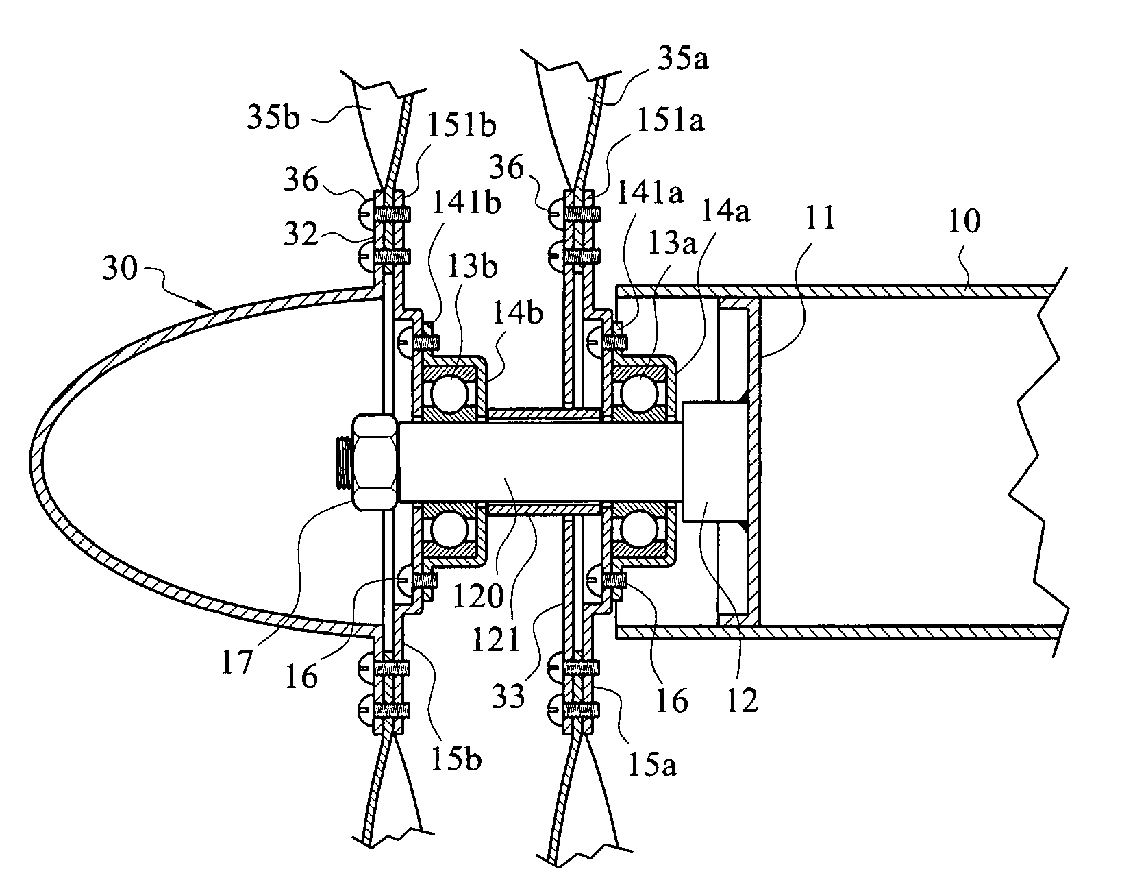
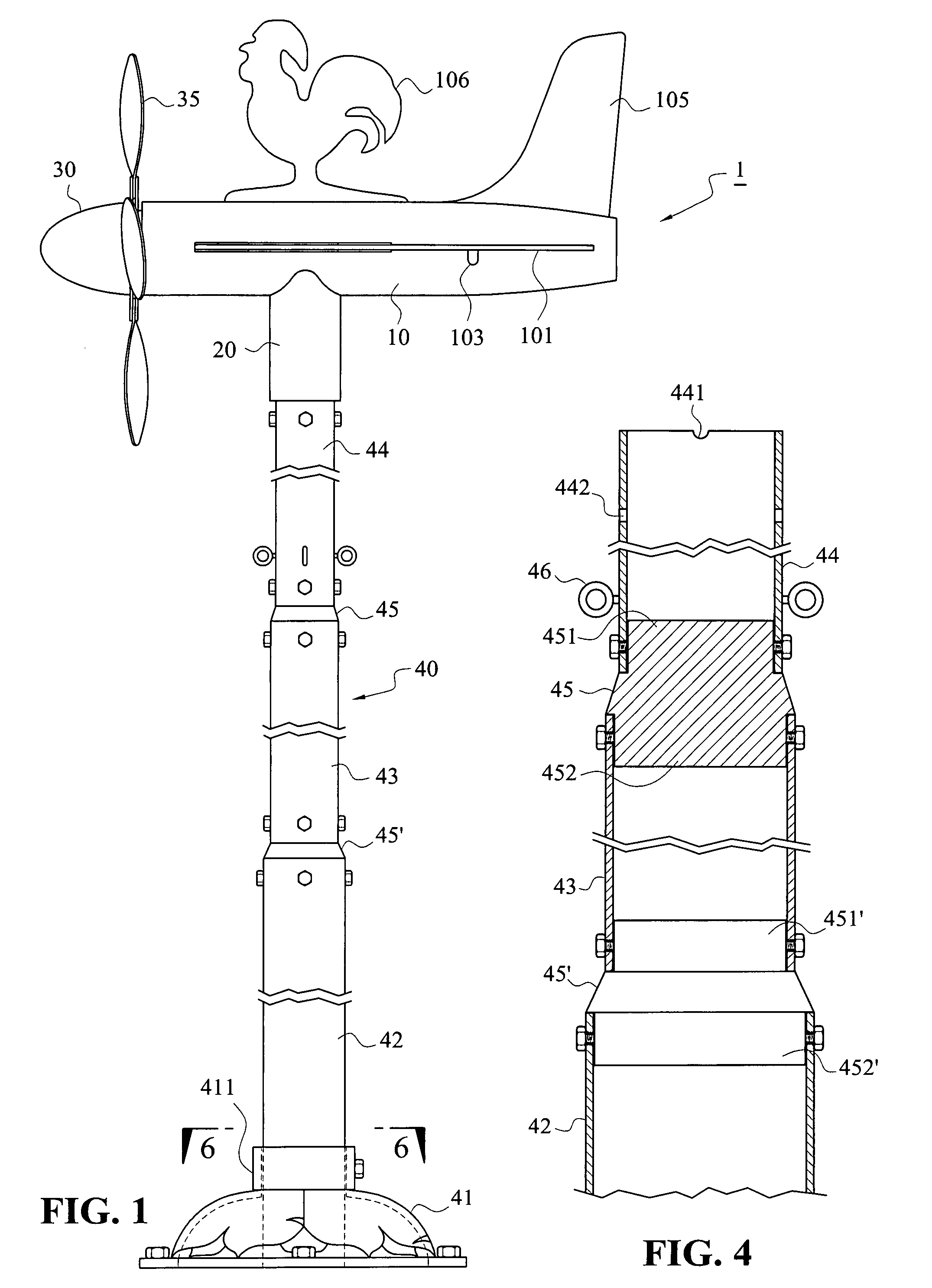
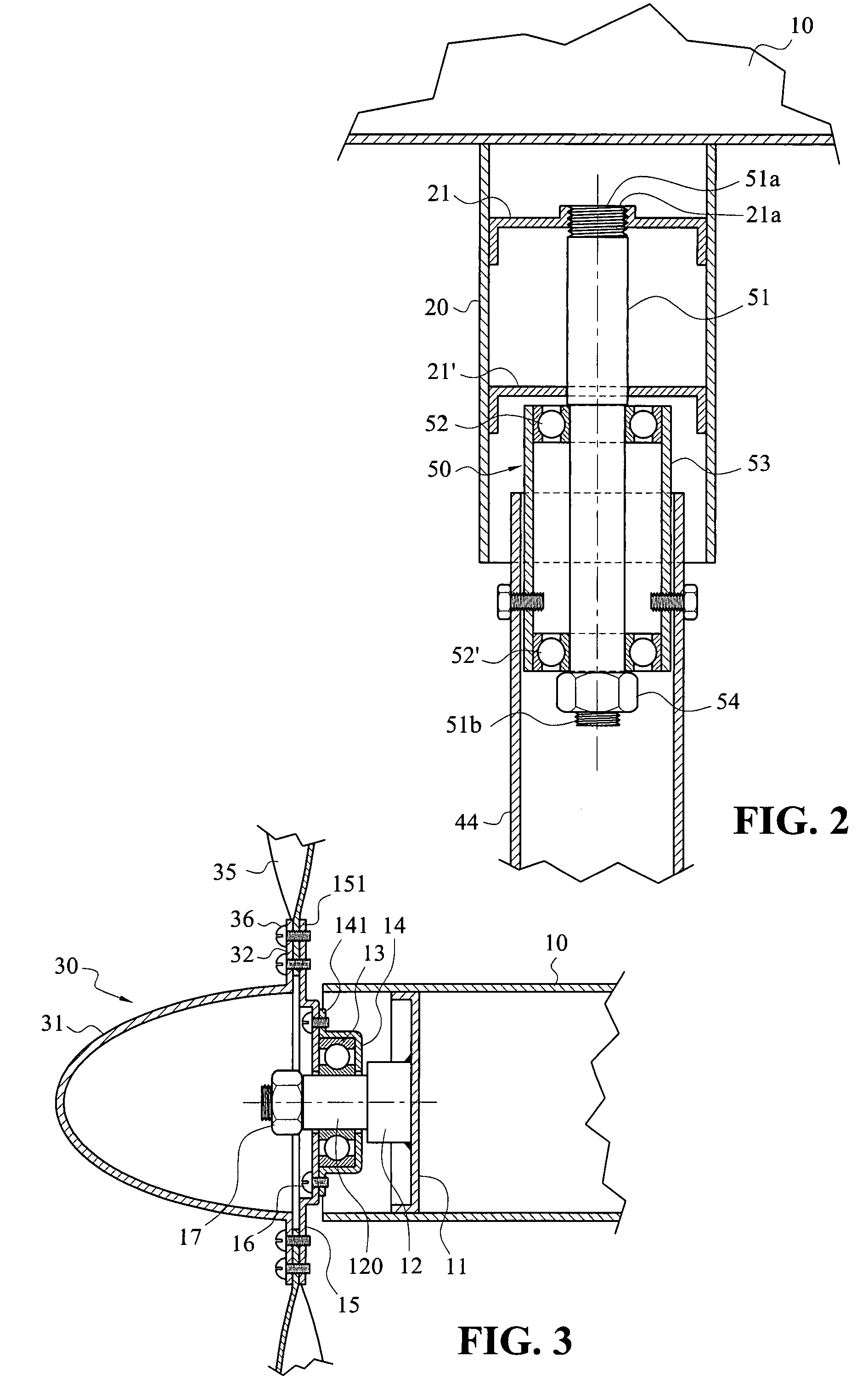
[0025]FIGS. 1 to 7 shows an embodiment of the wind vane device 1 of the present invention. The wind vane device 1 of this embodiment essentially comprises a horizontal portion 10, that can swivel by a plurality of blades 35 provided at one end, a vertical portion 20 with one end attached to the bottom of the horizontal portion 10 and the other end extending downwardly, a supporting frame 40 supported at the lower side of the vertical portion 20 (as shown in FIG. 1).

[0026]Referring to FIG. 2, the vertical portion 20 is a cylindrical structure and has a plurality of radial partitioning walls 21,21′ at the inner side in the axial direction. A suitable distance is maintained between the partition wall 21 and the partition ...


PUM


Abstract

A wind vane device comprises a horizontal portion that can swivel by the propeller blades provided at one end, a vertical portion with one end attached to the bottom of the horizontal portion and the other end extending downwardly, a supporting frame supporting the horizontal portion at the lower side of the vertical portion, wherein the vertical portion is cylindrical and has a plurality of radial partitioning walls at inner side in the axial direction; an upright shaft having an axle 51 with thread portions at both ends, one end of which is fastened to the center of the partitioning wall and the other end provided with a pair of bearings, a bearing sleeve being put around the outside of the pair of bearings; wherein the supporting frame consists of several sections of supporting rods. An engageable and disengageable structure is formed between a supporting rod and a supporting rods through a connector. The upper end located at the supporting rod of top-section engages at the outside of the bearing sleeve. In this manner, a structure easy for assembling / disassembling and transporting can be obtained.

Description

BACKGROUND OF THE INVENTION[0001]1. Field of the Invention[0002]The present invention relates to a wind vane device, more particularly to a large-sized wind vane device with DIY structure that is easy in assembling / disassembling and transportation thereof.[0003]2. Brief Description of the Prior Art[0004]Conventionally, a Taiwanese Patent No. M244449 entitled “Improved Device for a Wind Vane with Pattern”, as shown in FIG. 10, mainly comprises: a base (11′); a round tube (12′) supported at the center of the upper side of the base (11′), an orientation indicating plate (13′) being provided at the outside of the upper end of the round tube (12′), a plug having a V-shape recess being inserted in the inside at the top end of the orientation indicating plate (13′); a main shaft (14′),the lower end of which is acute, which is positioned in the V-shape recess to swivel; a disk (15′), the center of which is fixed on the top of the main shaft (14′) by a bow-shape support (16′); a cup set (17′...

Claims


Application Information

Patent Timeline
Patent Type & Authority Patents(United States)
IPC IPC(8): G01W1/00
CPCG01P5/06G01P13/02
Inventor CHEN, FU-LIANG
Owner CHEN FU LIANG
Why Eureka
Try Eureka