Modularized structure of switch wire connection device

a technology of modular structure and connection device, which is applied in the direction of coupling device connection, contact, coupling device details, etc., can solve the problems of conductive wire loosening and detachment from the case, troublesome operation of the operator, and easy loosening of screws, so as to facilitate assembly/disassembly of components and enhance the insulation

Active Publication Date: 2019-10-15
SWITCHLAB +1
View PDF4 Cites 3 Cited by
  • Summary
  • Abstract
  • Description
  • Claims
  • Application Information

AI Technical Summary

Benefits of technology

[0010]It is therefore a primary object of the present invention to provide a modularized structure of switch wire connection device includes an assembling support and a wire connection module. The assembling support has a first side and a second side. The first and / or the second sides are formed with assembling sections for assembling with the wire connection module. The wire connection module includes a first wire connection module and / or a second wire connection module each having a case. The case defines a chamber for receiving and enclosing electrical contact components including conductive members. The case is formed with a mounting section for connecting with the assembling section of the assembling support. Accordingly, the wire connection module is detachably mounted on the assembling support as an integrated form. The modularized structure enables an operator to easily assemble / disassemble the components and change the switch specification between normally open mode and normally closed mode and enhance insulation effect to avoid electric arc.
[0011]In the above modularized structure of switch wire connection device, the wire connection module includes a first wire connection module and a second wire connection module. The wire connection module (or the first and second wire connection modules) has a case. The case includes a main end wall, a mounting side and an enclosure side connected with the main end wall and a subsidiary end wall connected with the mounting side and the enclosure side. The main end wall and the mounting side are respectively formed with a main opening and a lateral opening in communication with the chamber, whereby the electrical contact components can be mounted into the chamber of the case. The first and second sides of the assembling support are respectively formed with restriction sections. The restriction sections can insert with the edge of the lateral opening of the case to help in fixing the wire connection module and the assembling support.
[0012]In the above modularized structure of switch wire connection device, the switch drum body (lower section) is formed with at least one or multiple notches. The lower section (or a section in adjacency to the subsidiary end wall) of the case (or the enclosure side) of the wire connection module is formed with an enlarged section in the position of the wire plug-in hole. The enlarged section is correspondingly assembled with the notch to enhance the assembling / fixing effect between the switch drum body and the wire connection module. In practice, the enlarged section allows the diameter of the wire plug-in hole to be enlarged, whereby a conductive wire with a larger diameter can be plugged into the wire plug-in hole.
[0013]It should be noted that in the condition that the operation room is limited, the enlarged section partially protrudes from the notch. When assembling / disassembling the switch drum body, the wire connection module and the relevant components, an operator can use a tool to securely hold the enlarged section so as to avoid unstable swing of these components.

Problems solved by technology

(Due to the limitation of the environment of the working site, the operator is often troublesome and hard to perform the operation).
Also, in some operation environments (such as the operation of the machine or the equipment will cause vibration), after a long term of use, the screw is apt to loosen.
As a result, the conductive wire may loosen and detach from the case.
Especially, when driving the screw mechanism to lock the conductive wires with the electrical contact, it is necessary to use a tool for tightening / untightening the screw.
Such process is relatively troublesome.
This means that in case of failure of the switch wire connection device, it is impossible to only replace the damaged part and it is necessary replace the entire switch wire connection device.
Accordingly, the cost of the user is relatively increased.
In addition, as well known by those who are skilled in this field, due to negligence of an operator, it often takes place that the normally open (NO) module and / or the normally closed (NC) module are incorrectly arranged to fail to meet the requirement of the user.
Especially, when the switch wire connection device is applied to a conductive wire with a specification of greater current, the structure of the contact seat often causes electric arc of the adjacent conductive components.
The electric arc will lead to unstable power transmission.
For example, in the condition that it is easy to manufacture and operate the structure of the switch wire connection device, it is necessary to improve the shortcomings of the conventional switch wire connection device that the operator necessitates a larger operation room and the operator must bend the conductive wire and when driving the screw mechanism to lock the conductive wires with the electrical contact component, it is necessary to use a tool for tightening / untightening the screw and such process is relatively troublesome and harder.

Method used


Image

  • Modularized structure of switch wire connection device
  • Modularized structure of switch wire connection device
  • Modularized structure of switch wire connection device

Examples


Embodiment Construction

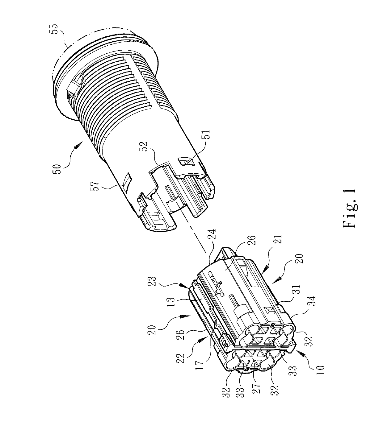
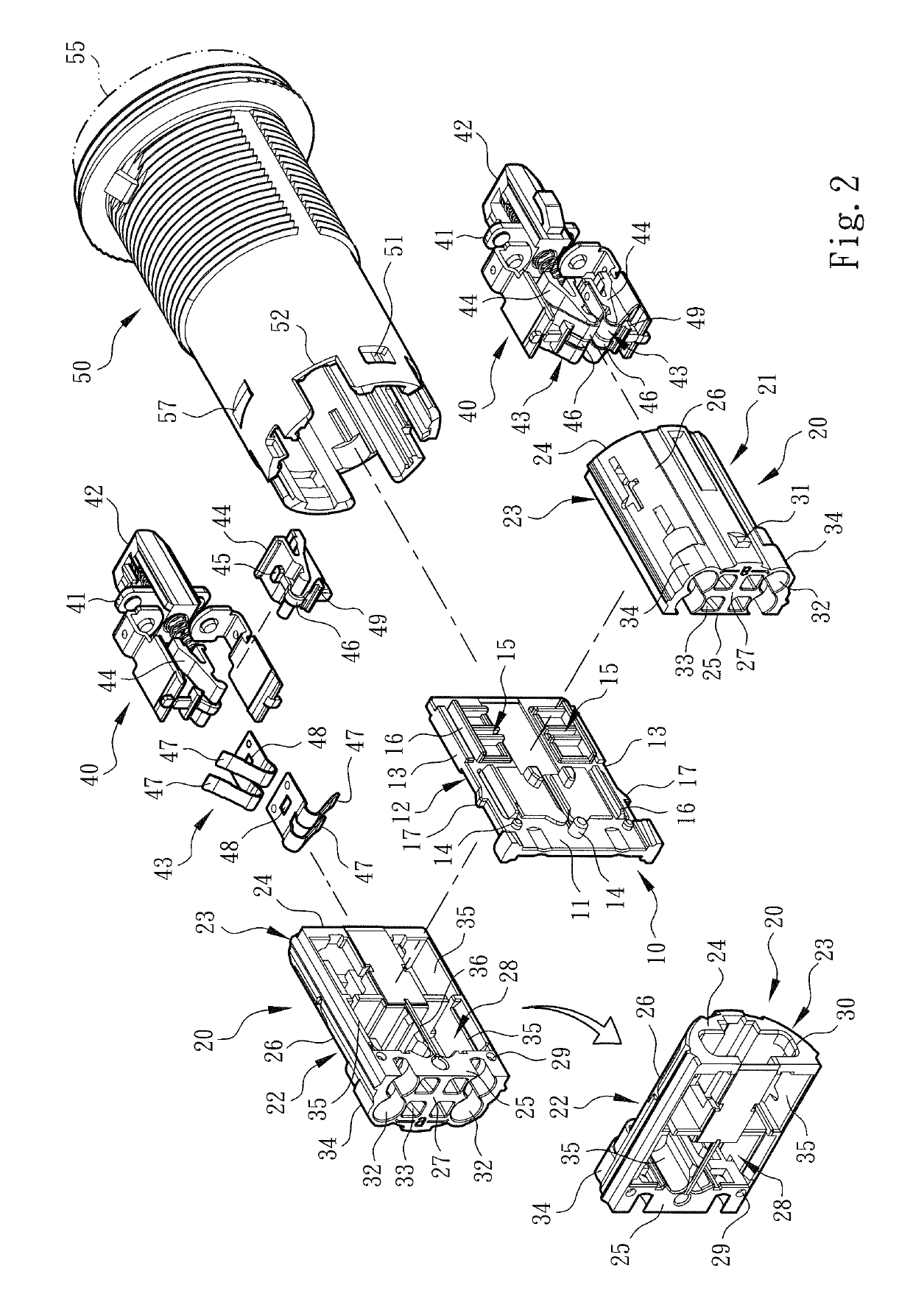
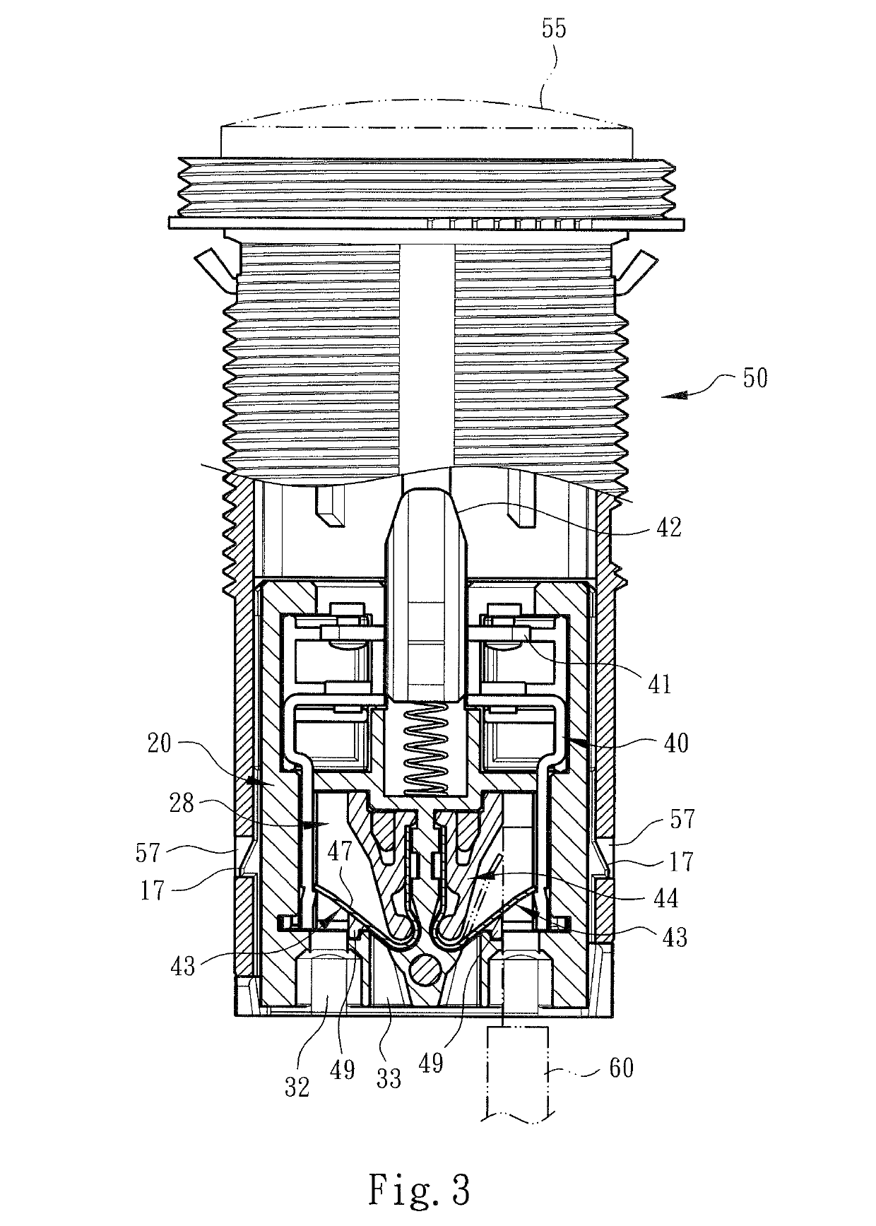
[0020]Please refer to FIGS. 1, 2 and 3. The modularized structure of switch wire connection device of the present invention includes an assembling support 10. The assembling support 10 has a first side 11, a second side 12 and lateral sides 13 connected with the first and second sides 11, 12. The first and second sides 11, 12 are respectively formed with boss-shaped assembling sections 14 for assembling with a wire connection module 20.

[0021]As shown in the drawings, the wire connection module 20 includes a first wire connection module 21 and a second wire connection module 22. The wire connection module 20 (or the first and second wire connection modules 21, 22) has a case 23 with a geometrical cross section or profile. The case 23 is a semi-cylindrical structure including a main end wall 24, a mounting side 25 and an enclosure side 26 connected with the main end wall 24 and a subsidiary end wall 27 connected with the mounting side 25 and the enclosure side 26 to together define a ...


PUM


Abstract

A modularized structure of switch wire connection device includes an assembling support and a wire connection module. The assembling support has a first side and a second side. The first and / or the second sides are formed with assembling sections for assembling with the wire connection module. The wire connection module includes a first wire connection module and / or a second wire connection module each having a case. The case defines a chamber for receiving and enclosing electrical contact components. The case is formed with a mounting section for connecting with the assembling section of the assembling support. The wire connection module is detachably mounted on the assembling support as an integrated form. The modularized structure enables an operator to easily assemble / disassemble the components and change the switch specification between normally open mode and normally closed mode and enhance insulation effect to avoid electric arc.

Description

BACKGROUND OF THE INVENTION1. Field of the Invention[0001]The present invention relates generally to a modularized structure of switch wire connection device, and more particularly to a modularized structure of switch wire connection device, which includes an assembling support and multiple modularized wire connection modules. The modularized wire connection modules are detachably mounted on the assembling support as an integrated body.2. Description of the Related Art[0002]A conventional switch wire connection device is a power switch device capable of connecting circuits or conductive wires. The switch wire connection device is installed on a console or distribution box of an electronic or electrical apparatus for connecting the wiring circuits. The switch wire connection device has a wire connection seat or contact seat (generally made of plastic material) and a conductive component mounted on the wire connection seat or contact seat and a screw for locking the wiring circuits or...

Claims


Application Information

Patent Timeline
Patent Type & Authority Patents(United States)
IPC IPC(8): H01H13/04H01R13/518H01R4/48H01H13/14H01H1/58H01R13/514H01H11/00H01R13/53
CPCH01H1/58H01H13/02H01H13/04H01H11/0012H01H1/5844H01H13/10H01R4/48275H01H13/14H01R13/53H01R13/518H01R13/514
Inventor WU, CHIH-YUANHSIAO, CHIH-KUNHSU, WEN-BING
Owner SWITCHLAB
Why Eureka
Try Eureka